Page 2 579-1032 Rev F
TrueAlert ES Addressable UL Listed Multi-Candela Weatherproof Notification Appliances Installation Instructions
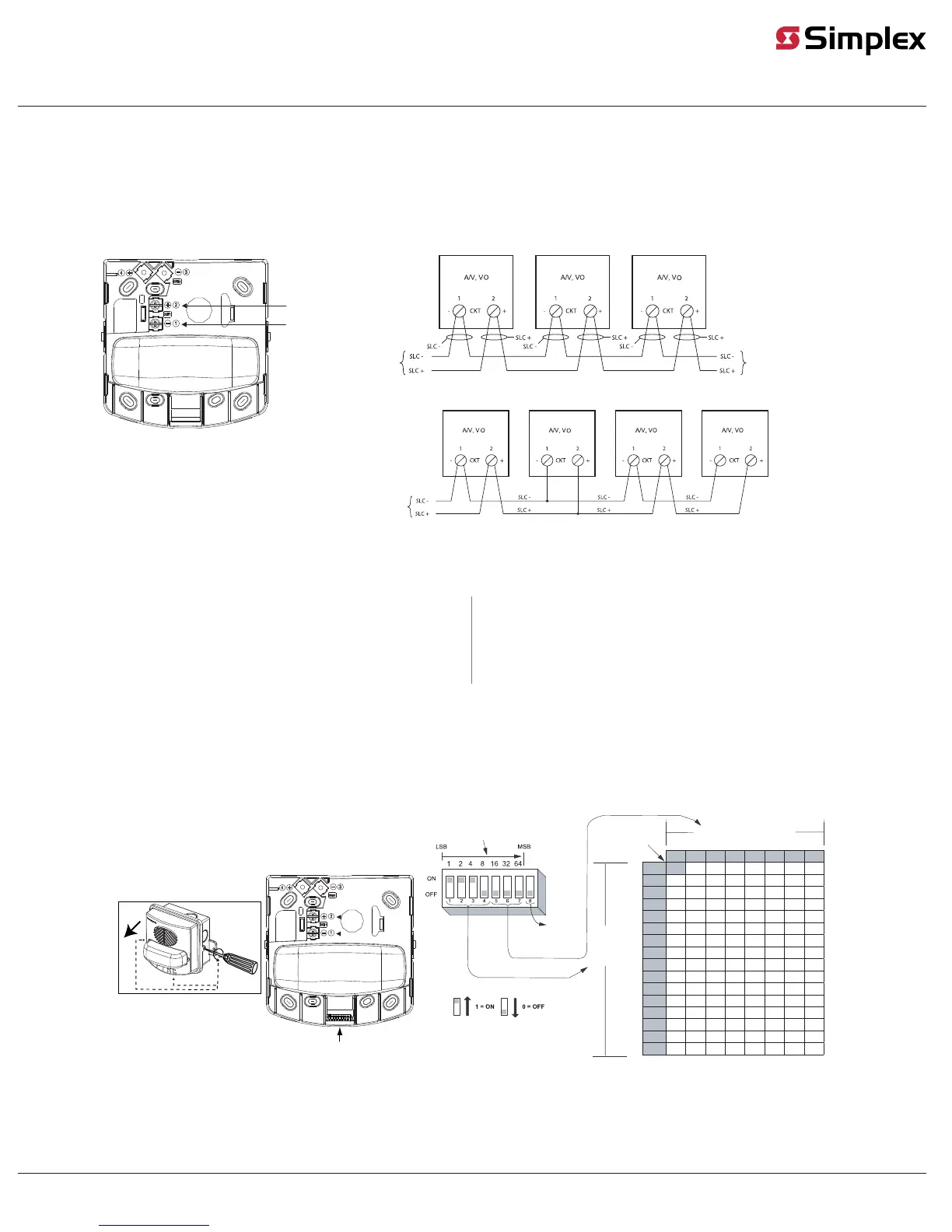
Wiring instructions
WARNING: Ensure that all power is disconnected before starting the installation.
1. At the electrical box, connect the contractor wiring to the CKT + and CKT - terminals at the front of the strobe unit.
2. To ensure proper continuity, use a torque wrench to tighten the terminal block screws to 12-15 inch-pounds.
3. Ensure that correct polarity is maintained for each strobe unit.
4. Signal line circuit (SLC) wiring must be twisted pair (TWP). CKT terminals accept two wires: 12-18 American Wire Gauge (AWG) TWP.
IMPORTANT: Do not bring the conduit through the rear of the electrical box. Strip the lead insulation to 3/8 inches maximum.
Wall mount VO and A/V appliance
Terminal 2
CKT+ input
Terminal 1
CKT- input
From compatible
SLC controller,
see notes
From compatible
SLC controller,
see notes
To the next appliance or
compatible SLC controller,
see notes
Class A wiring, see notes
Class B wiring, see notes
Fig 4: Wiring instructions
Wiring notes
• Assign a maximum of 63 devices to a circuit. The maximum devices with active appliances on a circuit is
50. The maximum wire resistance between appliances is 26 ohms. See the field wiring diagrams of the
driving compatible fire alarm control panel for further instructions.
• Notification appliances are rated using an individual module label.
• Maintain the correct polarity on the terminal connections.
• TrueAlert SLC wiring connections are supervised and power-limited.
• These appliances are rated to the operating voltage limits of 23-31 VDC. The appliance may fail to
operate as intended, and cause permanent damage to this equipment if it operates outside of these
limits.
• Only operate the TrueAlertES A/V and VO devices using a compatible power supply.
• T-tapping is not permitted on Class A wiring.
Setting the address
Each addressable TrueAlertES notification appliance has a unique address that is set using an eight-position DIP switch (SW1). Assign a unique SLC address in the range 1 to 127 (Figure 5). However, the total appliance
loading available may be less due to appliance current requirements.
To set the address, complete the following steps:
1. Remove the cover from the device. See Figure 5.
2. Use a non-metallic stylus, or the equivalent to set the switches.
3. Record the set address.
Address DIP switch (SW1)
To access the switch:
0 = ALARM/
1 = ALERT
Reserved for
future use
DIP switch values:
DIP
switches
1 through 4
The DIP switch shown is
set at address 7
DIP switches 5 through 7
000 100 010 110 001 101 011
0000
111
0 16 32 48 64 80 96
1000
112
1 17 33 49 65 81 97
0100
113
2 18 34 50 66 82 98 114
31100 19 35 51 67 83 99
0010
115
4 20 36 52 68 84 100 116
1010 5 21 37 53 69 85 101 117
6 220110 38 54 70 86 102 118
71110 23 39 55 71 87 103
0001
119
8 24 40 56 72 88 104 120
1001 9 25 41 57 73 89 105 121
0101 10 26 42 58 74 90 106 122
1101 11 27 43 59 75 91 107 123
12 280011 44 60 76 92 108 124
13 29 451011 61 77 93 109 125
14 30 46 620111 78 94 110 126
151111 31 47 63 79 95 127111
Fig 5: Setting the DIP switch address
 Loading...