Page 3 579-1032 Rev F
TrueAlert ES Addressable UL Listed Multi-Candela Weatherproof Notification Appliances Installation Instructions
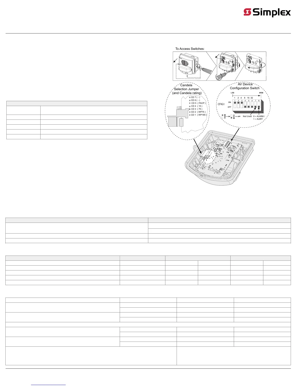
Setting the strobe candela setting
1. The jumpers are factory set to FACP. Use this setting when programming the candela setting at the
4100ES FACP. The candela setting is visible through the strobe lens.
2. For manual selection, pull up the jumper and position the pins to select the correct candela setting: 15,
75, WP75, WP185 candela or FACP.
Note: To avoid a programming mismatch trouble, an authorized service personnel must program one
of the four candela outputs for each appliance. For additional information, see the 4100ES Programmer’s
Manual (574-849).
Setting the device configuration
Use the Device Configuration switch (SW3), on the back of the device, to configure certain options for the
horn and strobe directly on the device. See Figure 6.
A/V only
Position 1
Configuration Control: OFF to enable Local Audible control (positions 2-7 below),
ON for Panel control.
Position 2 Audible Volume: High (OFF), Low (ON).
Position 3 CAN Horn mode: switch must be set to OFF.
Position 4 Legacy NAC mode: switch must be set to OFF.
Position 5, 6, 7 These switches must be set to OFF.
Position 8 Strobe Clear/Color domes: switch must be set to OFF.
CD 5 ( FACP )
CD 4 ( 15 )
CD 3 ( 75 )
CD 6 ( - )
CD 7 ( - )
CD 2 ( WP75 )
CD 1 ( WP185 )
Candela
Selection Jumper
(and Candela rating)
AV Device
Configuration Switch
To Access Switches:
0 = ALARM /
1 = ALERT
Not Used
CFIG1
Fig 6: Setting the strobe and device configuration
Device specifications
Table 1: Environmental specifications
Rated voltage range Special application 23-31 VRMS
WP75/WP185: -31
o
F to 151
o
F (-35
o
C to +66
o
C)
Temperature range
Other: 32°F to 120°F (0°C to 49°C)
Humidity range 10% to 98%, non-condensing at 104°F (40°C)
Connections Terminal for 18 AWG to 12 AWG (0.82 mm² to 3.31 mm²)
Table 2: UL1638 candela (CD) ratings
Straight out from unit Vertical below unit (Left/right) horizontal)
Angle 0° 45° 90° 45° 90°
WP75 minimums (over temperature range) 75 69 17 60 28
WP 75 typical CD (at 25°C) 165 86 22 74 35
WP185 minimums (over temperature range) 185 90 21 81 40
WP185 typical CD (at 25°C) 220 112 27 101 50
Table 3: Sound pressure level measurement (dBA)
Reverberant room at ten feet in accordance with UL464 (See Note 2) Voltage (Vrms) Horn Mode Steady Horn Mode Coded (See Note 1)
23 (Min.) 81.3 76.4
High volume setting using addressable controller (See Note 3)
31 (Max.) 82.1 78.8
23 (Min.) 73.8 69.9
Low volume setting using addressable controller (See Note 3)
31 (Max.) 77.0 72.2
Anechoic room at 10 feet in accordance with ULC S525
23 (Min.) 87.4 87.2
High volume setting
31 (Max.) 89.2 89.2
23 (Min.) 81.0 80.6
Low volume setting
31 (Max.) 84.0 82.8
Note
1. The coded category covers both Temporal and March time cadences.
2. Reverberant dBA measurements are a minimum UL rating based on sound power level measurements made in UL’s
reverberant test chamber.
3. High and low volume settings are configured with DIP Switch (SW4) on the
controller.
4. Settings with ratings below 75dB should only be used for Private Mode Notification.
 Loading...