Initial Turbo Installation
6
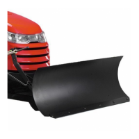
Install Deflector
1. See Figure 6. Drill four 13/64” holes from the bottom
of the deflector at the pre-molded drill points (A, bot-
tom of deflector).
2. Attach the deflector to the support rod wire-form
using four #10-14 x 3/4 truss head screws and nylock
nuts.
A
C
B
Figure 6. Install Deflector
A. 13/64 Hole Locations C. Screws, #10-24 x 3/4
B. Nylock Nuts
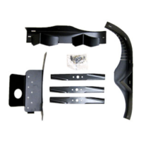
Install Belt Guide
1. See Figure 7 & 8. Locate the taptite screw that will
be replaced by capscrew (C). Remove and discard
the taptite screw
2. Assemble the 5/16-18 x 1-1/2 capscrew (C), lock-
washer (E), washers (B), belt stop (D) and spacer
(A).
3. Secure the belt stop assembly to the deck in the loca-
tion shown.
Note The belt stop (D, Figures 7 & 8) is located and ori-
ented differently in 44” and 50” applications. For all
applications, when turbo is installed, beld stop (D) should
be outside the belt 1/8” away from the backside of the
belt.
C
E
D
A
Figure 8. Install Belt Guide
A. Spacer D. Belt Stop
B. 5/16 Washers E. Lockwasher,
C. Capscrew, 5/16-18 x 1-1/2 5/16
B
44” Models
C
E
D
A
Figure 7. Install Belt Guide
A. Spacer D. Belt Stop
B. 5/16 Washers E. Lockwasher,
C. Capscrew, 5/16-18 x 1-1/2 5/16
B
50” Models