33
Neutral Adjustment
Perform the following adjustment if the shift lever
must be moved out of the neutral gate to prevent
forward or reverse rider movement. With the shift
lever in the neutral gate and the clutch/brake pedal
released, a small amount of travel in the shift lever
may be required to fully stop rider.
1. Position rider on flat level ground and start rider.
2. With engine running, position the shift lever so
that the rider has no forward or reverse move-
ment (shift lever may not necessarily be in the
neutral gate). Shut off the rider engine and do not
depress clutch/brake pedal or move shift lever.
Alternate method: Raise rear wheels off ground
and support rider frame with jackstands. Move
shift lever forward and reverse and then move
shift lever so that rear wheels do not rotate.
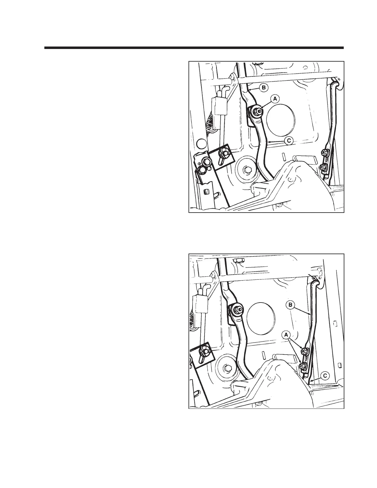
3. Loosen the nut (A, figure 11-1) that secures the
front hydro control rod (B) to the rear rod (C).
Control rod must be free to move. If performing
the return-to-neutral adjustment, loosen the two
nuts (A, figure 11-2) that secure the front return-
to-neutral rod (B) to the rear rod (C). Front
return-to-neutral rod must be free to move.
4. Move the shift lever into the neutral gate.
5. Tighten the nut (A) securely to 17 ft. lbs.
6. Check operation of rider for any movement with
shift lever in neutral gate. Perform the return-to-
neutral adjustment (refer to following para-
graph).
Return to Neutral Adjustment
Perform the following adjustment if the shift lever
does not return to the neutral gate when the clutch/
brake pedal is fully depressed. Make sure the front
hydro control rod (B, figure 11-1) is lubricated and
does not bind in the carrier frame hole.
1. Make sure the Neutral Adjustment is correct
(refer to preceding paragraph).
2. Loosen the two nuts (A, figure 11-2) that secure
the front return-to-neutral rod (B) to the rear rod
(C). Front return-to-neutral rod must be free to
move.
3. Place the shift lever in the full forward position
(highest ground speed setting in the transport
quadrant).
4. Move the front return-to-neutral rod all the way
rearward in the slot to shorten the length of the
assembled return-to-neutral rods. Tighten the
two nuts (A) with rods in this position.
5. Start the rider and check the return-to-neutral
operation.
Section 11.
Mid-Engine Riding Mowers with HydroGear 311-0500
Figure 11-1. Neutral Adjustment
A. Nut
B. Front Hydro Control Rod
C. Rear Hydro Control Rod
Figure 11-2. Return-to-Neutral Adjustment
A. Nut
B. Front Return-to-Neutral Rod
C. Rear Return-to-Neutral Rod
*2425
*2425

 Loading...