This manual describes the Simplicity Sno-Away 23" Self-Propelled Rotary Snow Thrower, Article No. 990221, a robust machine designed for efficient snow removal. The manual provides comprehensive instructions for assembly, operation, and maintenance, ensuring users can effectively utilize and care for their snow thrower.
Function Description
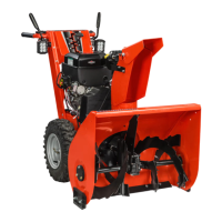
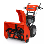
The Simplicity Sno-Away is a self-propelled rotary snow thrower, meaning it moves under its own power, reducing the effort required from the operator. Its primary function is to clear snow from various surfaces, such as driveways, sidewalks, and paths. The "rotary" aspect indicates that it uses a rotating auger to collect and throw snow through a discharge spout. The "23-inch" specification refers to the width of the clearing path, making it suitable for medium to large snow removal tasks. The engine, identified as a Lauson Eng. H-35P-2404, provides the power for both the self-propulsion and the snow-throwing mechanism.
The snow thrower features a two-stage design, common in rotary snow throwers. The first stage involves an auger (part of the Rotor Group) that scoops up the snow and feeds it into the machine. The second stage consists of an impeller (not explicitly detailed but implied by the "rotary snow thrower" designation) that then propels the snow out through the discharge spout. This two-stage process is highly effective for handling various types of snow, from light powder to heavy, wet snow.
The self-propelled feature is managed by a transmission system that drives the wheels. The operator can control the direction of travel (forward or reverse) and the engagement of the transmission clutch. This allows for easy maneuvering and reduces physical strain, especially when clearing large areas or dealing with deep snow.
Usage Features
The Simplicity Sno-Away is designed with several features to enhance its usability and operational efficiency:
Assembly and Initial Setup:
The snow thrower is shipped in one carton with the handles and discharge spout removed, requiring some initial assembly. The manual provides clear, step-by-step instructions for this process.
- Handle Attachment: The right and left handles are securely fastened to mounting brackets using hex cap-screws, flat washers, lockwashers, and hex nuts.
- Control Rods: The spout adjusting handle, shift rod, and clutch rod are attached to the upper end of the handles. The shift rod connects to a lever "A" with a cotter pin, while the clutch rod connects to an idler pulley with a hex lock nut, allowing for free pivoting.
- Discharge Spout Installation: The discharge spout is installed on the rotor housing after applying a light oil to its mounting collar to prevent rust and ensure free rotation. A "V" belt is clamped around the spout and looped around an adjusting pulley, with its lower end connected to the spout adjusting handle. Tension of this belt can be adjusted via a hex nut at point "A" on the spout assembly.
Operational Controls:
The snow thrower offers intuitive controls for managing its functions:
- Rotor Clutch: The operation of the rotor is controlled by a foot pedal. Raising the foot pedal engages the rotor clutch, activating the snow-throwing mechanism. Depressing the pedal disengages it. This independent control allows the operator to stop the rotor without stopping the engine or the self-propulsion.
- Transmission Shift Lever: The direction of travel (forward or reverse) is controlled by the transmission shift lever, located on the handles. The manual emphasizes disengaging the transmission clutch before shifting. Pushing the lever forward engages forward travel, while pulling it back engages reverse. A detent lever holds the shift lever in the neutral position, which is halfway between forward and reverse.
- Throttle Control: The engine's throttle control knob is used to stop the engine by moving it all the way to the shut-off position.
- Discharge Spout Adjustment: The direction and height of the discharged snow can be adjusted. The spout can be rotated to direct snow to the left or right. For vertical adjustment (throw height), the spout extension and raising or lowering the extension can be adjusted by loosening wing nuts on the spout adjusting handle. This allows the operator to tailor the snow discharge to specific conditions and avoid throwing snow into unwanted areas.
- Self-Propelled Operation: The self-propelled feature allows the snow thrower to move through snow with minimal effort. The operator simply guides the machine, and the transmission system handles the propulsion. The manual advises putting the transmission clutch in the disengaged position when shifting gears.
Safety Features and Precautions:
The manual stresses several safety points:
- Engine Operation: Before starting or operating, users must refer to the engine manufacturer's owner's manual for proper fuel, oil, and starting procedures.
- Rotor Safety: It is crucial to never attempt to remove snow or ice from the rotor housing or discharge spout unless the engine is stopped and the rotor clutch is disengaged. This prevents serious injury from the rotating auger.
- Obstruction Caution: The manual includes a "CAUTION" section warning operators to avoid any foreign material or obstructions in the snow. If an obstruction occurs, the engine should be shut off, and the rotor clutch disengaged immediately before attempting to remove the obstruction. This prevents damage to the machine and potential injury.
- Operating in Heavy Drifts: When operating through heavy drifts, the manual suggests depressing the handles and raising the rotor housing while taking the first pass through the drift. Subsequent passes can be made with the rotor housing lowered. This method helps manage heavy snow loads more effectively.
- Cold Weather Operation: After completing snow plowing, the manual recommends allowing the machine to run for about 5 minutes to dry out and prevent the formation of ice. This helps prevent snow from freezing to the machine, which could impede future operation.
Maintenance Features
Proper maintenance is essential for prolonging the life and ensuring the reliable operation of the Simplicity Sno-Away. The manual outlines several key maintenance procedures:
Belt Tension Adjustment:
The snow thrower relies on several "V" belts for power transmission, and maintaining correct tension is critical.
- Rotor Drive Belt: Tension is regulated by the position of a set collar on the rotor clutch rod. A 1/2" clearance between the set collar and clutch rod clip is the normal setting when the rotor clutch is disengaged. To increase tension, the set screw in the collar is loosened, the collar is slid toward the spring on the clutch rod, and then the set screw is retightened. Over-tensioning should be avoided to prevent premature belt failure.
- Transmission Drive Belt: Tension is regulated by the position of a set collar on the transmission clutch rod. A 1/4" clearance between the set collar and the clutch rod clip is the normal setting when the clutch is engaged. The adjustment procedure is similar to the rotor drive belt: loosen the set screw, slide the collar toward the spring, and retighten. Again, excessive tension should be avoided.
Chain Tension Adjustment:
The rotor drive chain tension can be adjusted to ensure smooth operation and prevent slippage.
- Adjustment Procedure: Tension is increased by loosening two lock nuts "A" and turning adjusting nuts "B" to the desired position. After adjustment, the lock nuts "A" must be retightened.
Belt Stops Adjustment:
Belt stops are crucial for proper belt disengagement and engagement.
- Adjustment Procedure: Three belt stops are located on the drive pulley side of the engine. When the Rotor Clutch and Transmission Clutch are engaged, there should be a 1/16" clearance between the belts and the belt stops. To adjust, the hex capscrews holding the stops are loosened, the stops are repositioned to achieve the correct clearance, and then the hex capscrews are retightened.
Lubrication:
Regular lubrication is vital for reducing wear and ensuring smooth operation of moving parts.
- Grease Fittings: The snow thrower is equipped with four grease fittings that require occasional lubrication with a general-purpose automotive grease. The locations of these fittings are clearly indicated in the assembly diagrams (Figures 1, 3, and 7).
- Rotor Shaft Bearings: The bearings on the rotor shaft are sealed and do not require further lubrication. However, an occasional application of light motor oil to the ends of the rotor shaft seals is recommended to prolong their life.
General Maintenance Advice:
- Engine Maintenance: The manual directs users to the engine manufacturer's owner's manual for specific engine maintenance requirements, including fuel and oil specifications.
- Storage: While not explicitly detailed as a maintenance feature, the advice to run the machine for 5 minutes after use in cold weather implies a recommendation for proper storage preparation to prevent ice buildup and rust.
By following these detailed instructions for assembly, operation, and maintenance, users can ensure their Simplicity Sno-Away 23" Self-Propelled Rotary Snow Thrower remains a reliable and effective tool for snow removal for many seasons.