Paragraph
1.1
1.2
1.3
1.4
1.5
1.6
2.1
2.2
2.3
3.1
3.2
3.3
3.4
3.5
4.1
4.3
4.3
4.4
4.5
4.6
5.1
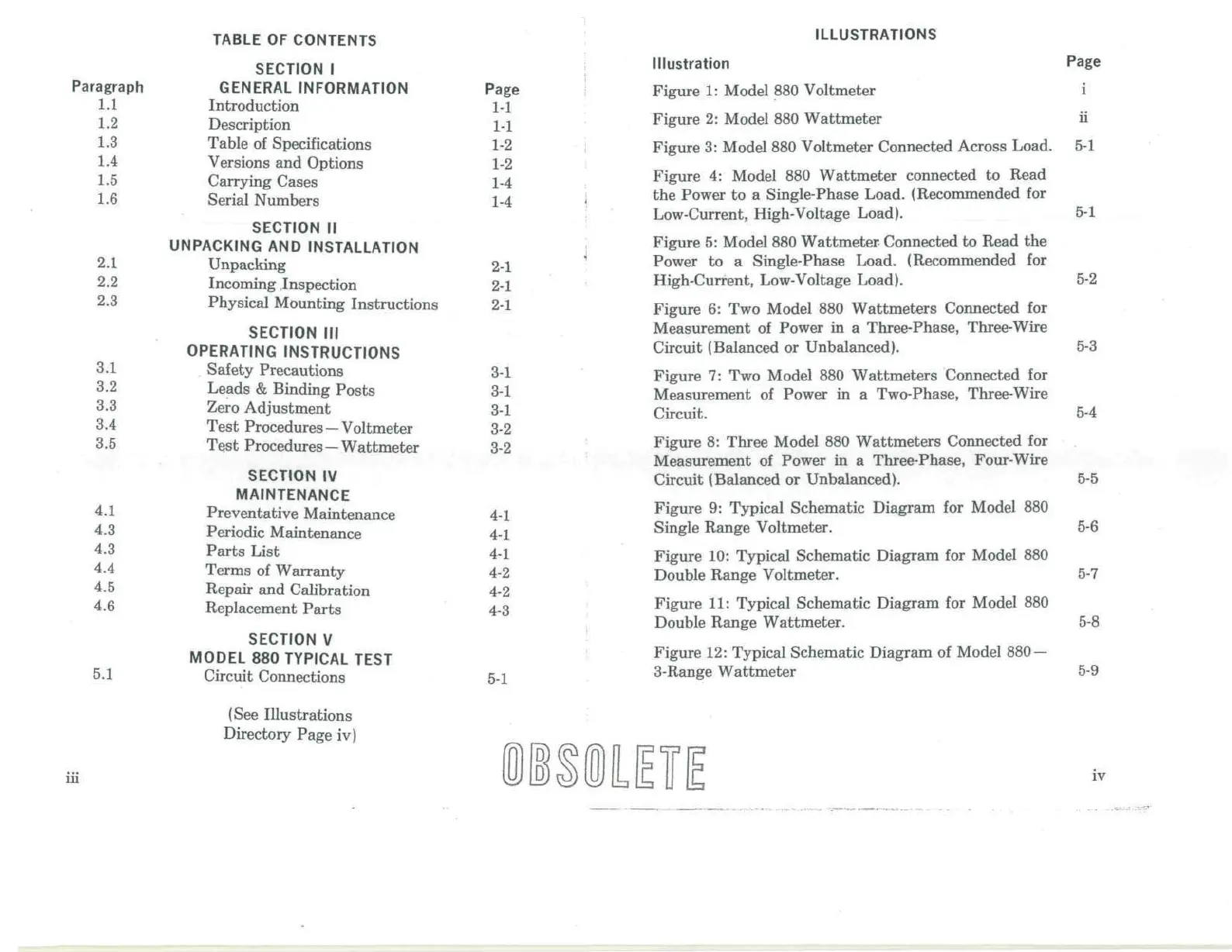
TABLE
OF
CONTENTS
SECTION
I
GENERAL
INFORMATION
Introduction
Description
Table
of
Specifications
Versions
and
Options
Carrying Cases
Serial Numbers
SECTION
II
UNPACKING
AND
INSTALLATION
Unpacking
Incoming
.Inspection
Physical Mounting Instructions
SECTION
III
OPERATING
INSTRUCTIONS
Safety
Precautions
Leads
&
Binding
Posts
Zero
Adjustment
Test
Procedures
—Voltmeter
Test
Procedures
—Wattmeter
SECTION
IV
MAINTENANCE
Preventative Maintenance
Periodic Maintenance
Parts
List
Terms
of
Warranty
Repair
and
Calibration
Replacement
Parts
SECTION
V
MODEL
880
TYPICAL
TEST
Circuit
Connections
(See
Illustrations
Directory Page
iv)
Page
1-1
1-1
1-2
1-2
1-4
1-4
2-1
2-1
2-1
3-1
3-1
3-1
3-2
3-2
4-1
4-1
4-1
4-2
4-2
4-3
5-1
ILLUSTRATIONS
Illustration
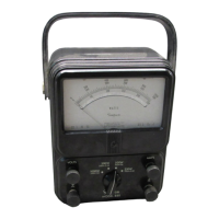
Figure
1:
Model
880
Voltmeter
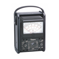
Figure
2:
Model
880
Wattmeter
Figure
3:
Model
880
Voltmeter Connected Across Load.
Figure
4:
Model
880
Wattmeter connected
to
Read
the
Power
to a
Single-Phase Load. (Recommended
for
Low-Current,
High-Voltage
Load).
Figure
5:
Model
880
Wattmeter
Connected
to
Read
the
Power
to a
Single-Phase
Load. (Recommended
for
High-Current,
Low-Voltage
Load).
Figure
6: Two
Model
880
Wattmeters
Connected
for
Measurement
of
Power
in a
Three-Phase,
Three-Wire
Circuit
(Balanced
or
Unbalanced).
Figure
7: Two
Model
880
Wattmeters
Connected
for
Measurement
of
Power
in a
Two-Phase, Three-Wire
Circuit.
Figure
8:
Three Model
880
Wattmeters Connected
for
Measurement
of
Power
in a
Three-Phase, Four-Wire
Circuit (Balanced
or
Unbalanced).
Figure
9:
Typical Schematic Diagram
for
Model
880
Single Range Voltmeter.
Figure
10:
Typical Schematic Diagram
for
Model
880
Double
Range Voltmeter.
Figure
11:
Typical Schematic Diagram
for
Model
880
Double
Range Wattmeter.
Figure
12:
Typical Schematic Diagram
of
Model
880
—
3-Range
Wattmeter
Page
11
5-1
5-1
5-2
5-3
5-4
5-5
5-6
5-7
5-8
5-9
in
iv