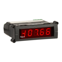
DISPLAY
Type:
7-segment red LED
Height: 0.56” (14.2mm)
Display resolution: 0.1º from -99.9º to 999.9º;
1.0º below -100º or above 1000º; 0.1mV for mV
indication
Open or faulty input connection: “----”
Uncalibrated instrument:
Display will flash continuously "INFO FAIL CALB
REQD" upon application of power.
Polarity:
Automatic, with “-” indication; “+” indication
implied
POWER REQUIREMENTS
AC Voltage:
85-250VAC @50-60Hz
Power Consumption: 2VA
Overrange indication (T/C or mV): The left-
most digit shows 1: "1" (other digits are blank)
INPUTS
Thermocouple:
J, K
Millivolt:
±70mV (uncompensated for temperature)
Lead Resistance Effect: -13V/100 max.
RTD: Platinum 100 Ohm (.00385 alpha)
Lead Resistance Effect:
4-wire: -.26C/100V max.
2- and 3-wire: 1C/.29 max.
Temperature Coefficient: ±0.2C / C
Input Impedance: 22M
Input Type Temperature Range Accuracy @258C
K T/C -100 to 1370C (0.1% rdg +1.5C)
-148 to 2498F (0.1% rdg +2.7F)
J T/C -100 to 1200C (0.1% rdg +1.5C)
-148 to 2192F (0.1% rdg +2.7F)
RTD Pt100 -100 to 850C (0.2% rdg +1.5C)
(4-wire) -148 to 1562F (0.2% rdg +2.7F)
mV -70 to 70mV (0.1% rdg +0.1mV)
(+0.1mV)
Specifications
Wiring Display
Input Selection
TERMINAL
1 2
INPUT (+)
INPUT (-)
5 6
BRIGHTNESS
(Short to Adjust)
TERMINAL
7 8
LINE VOLTAGE
RTD
RED (+)
WHITE( )
TERMINAL
RED (+) (3 WIRE AND 4 WIRE RTD'S)
WHITE ( )(4 WIRE RTD'S ONLY)
JUMPER (FOR 2 WIRE RTD ONLY)
JUMPER FOR 2 AND 3 WIRE RTD
1
234
Power Supply: Connect the power supply to terminals #7 and #8 as
shown above.
Display Adjust: Connect a short between terminals 5 and 6 as
shown. Shorting these terminals will cause the display to continuously
cycle through 6 levels of brightness. When the desired brightness level
is attained, remove the short. The selected brightness level is stored in
memory and will be maintained. To readjust brightness level, repeat the
above procedure.
NOTE: Recalibration is not required after an input change. If
desired, however, procedure is available from Technical Support.
Input Type JU1 JU2 JU3 JU4
J T/C, C IN OUT OUT IN
J T/C, F IN IN OUT IN
K T/C, C IN OUT OUT OUT
K T/C, F IN IN OUT OUT
RTD Pt100, C OUT OUT IN OUT
RTD Pt100, F OUT IN IN OUT
mV IN OUT IN IN
All Mini-Max Temperature Indicators are configured initially per the
customer specifications. Should the application change, the input type
can be changed as follows:
See diagram at right for jumper locations.
ENVIRONMENTAL
Operating Temperature:
0 to 55°C
Storage Temperature: -10 to 60°C
Relative Humidity: 0 to 85% non-condensing
Warmup time: Less than 20 minutes
ANALOG TO DIGITAL CONVERSION
Technique:
12 bit Successive Approximation (SAR)
Rate: 10 samples per second.
NOISE REJECTION
NMRR:
60dB, 50/60Hz
MECHANICAL
Bezel:
0.94” x 2.83”
(24mm x 72mm)
Depth: 2.36”(60mm)
Panel cutout: 0.89” x 2.71”
(22.2mm x 68mm)
Weight: 3.5oz (99.2g)
Case Material: