Do you have a question about the Simpson 260 Series and is the answer not in the manual?
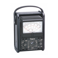
Provides a general overview of the Simpson 260 Series 7P and 7PM instruments.
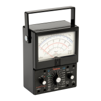
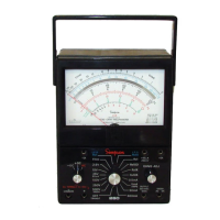
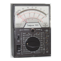
Details the features and construction of the Simpson 260 Series instruments.
Explains the types and function of the internal batteries used for ohmmeter circuits.
Describes the procedure to test the overload circuit functionality for safety.
Highlights the use of a printed circuit board for assembly and maintenance.
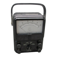
Details the durable phenolic case design for component protection.
Explains the carrying handle and its role in instrument positioning for viewing.
Describes the furnished test leads, probes, and alligator clips for measurements.
Lists detailed technical specifications including ranges, sensitivity, and voltage drops.
Explains how instrument accuracy is expressed and how to select ranges for better readings.
Alerts users to hazardous operating conditions and important safety warnings.
Explains the intended use and limitations of high voltage probes for extending measurement range.
Details the specifications and compatibility of accessory DC high voltage probes.
Describes the AC high voltage probe and its use with the 260-7P.
Explains the function and use of the Amp-Clamp for AC current measurements.
Covers general information and instructions for instrument installation.
Instructions for examining the instrument upon receipt and checking included items.
Directs users to the warranty policy details for repairs and service.
Provides guidelines for properly packing and shipping the instrument.
Specifies the internal batteries required for the ohmmeter circuits and their installation.
Discusses how to position the instrument for easy viewing and accurate readings.
Introduces the operating and adjustment controls, jacks, and indicators on the instrument.
Details the specific controls, jacks, and indicators found on the instrument's front panel.
Provides essential information for safe and proper use of the instrument.
Lists important safety suggestions and reminders for operating the instrument.
Explains how to use the function switch to reverse internal battery polarity.
Guides users on how to safely measure unknown voltage or current values.
Details how to use the test leads and alligator clips for safe and effective measurements.
Step-by-step instructions for measuring DC voltage in the 0-250 mV range.
Step-by-step instructions for measuring DC voltage in the 0-1V range.
Instructions for measuring DC voltage across multiple ranges from 2.5V to 500V.
Guidance for safely measuring high DC voltages up to 1000V.
Instructions for measuring AC voltage across multiple ranges from 2.5V to 500V.
Guidance for safely measuring high AC voltages up to 1000V.
Explains how to measure the AC component of mixed AC/DC voltage outputs.
Details how to perform decibel measurements using the instrument's dB scale.
Provides essential warnings and guidelines for all direct current measurements.
Step-by-step instructions for measuring DC current in the 0-50 microampere range.
Instructions for measuring DC current across ranges from 1mA to 500mA.
Guidance for measuring high DC currents up to 10 amperes.
Explains how to measure resistance and the importance of zero adjustment.
Provides detailed steps for performing resistance measurements using the instrument.
Details how to measure resistance of semiconductors like diodes and transistors.
Introduces topics covered in operator servicing, including maintenance.
Guidelines for regularly inspecting the instrument for damage and safety.
Instructions for replacing the internal batteries for resistance measurements.
Details how to replace the internal fuses for circuit protection.
Recommends periodic inspection of test leads for cuts, burns, or deterioration.
Provides advice on cleaning, storing, and maintaining the instrument.
General information for qualified personnel performing instrument servicing.
Step-by-step guide for gaining access to the instrument's internal components.
Information on obtaining replacement parts and understanding the schematic diagram.
| Brand | Simpson |
|---|---|
| Model | 260 Series |
| Category | Measuring Instruments |
| Language | English |