7
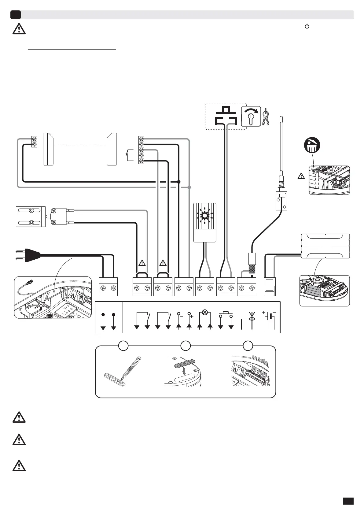
Connecting peripherals
7
Description of the various peripherals
1 - 24V Amber light
2 - Keyswitch (operation in sequential mode)
3 - Remote Aerial
4 - Back-up battery
5 - Pedestrian door safety kit
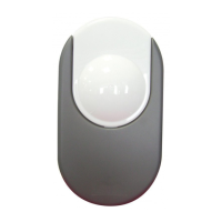
6 - Photoelectric cells
Cut the electric power supply to the motor before performing any work on peripherals. The indicator light
remains off
after working on the system, check the wiring (for possible short circuits or polarity reversals).
* Pedestrian door safety kit (5): When the pedestrian door contact is fi tted, it must be connected in place of the jumper normally
fi tted between terminals 3 and 4. If the pedestrian door contact is removed, the jumper between terminals 3 and 4 must be refi tted.
** Photoelectric cells (6): When fi tting photoelectric cells, connect the receiver cell (CR) to the input in place of the jumper fi tted
between terminals 5 and 6. If the cells are removed, the jumper between terminals 5 and 6 must be refi tted.
*** Remote aerial (3): When using the remote aerial, remove the wire standard aerial.
Passage of wires
Transmitter cell Receiver cell
Sec.
65
24Vdc
Flash
109
Ant.
141387
Stop
43
Start
Batt.
161512
11
230V
50-60Hz
LN
21
3
2
1
5
6
1
***
***
4
1
2
3
4365871091211 1413
2
1
2
3
NF
4
5