47
47
47
47
660
590
660
5
5
5
673
603
673
693
623
693
47
47
47
590 5 603 623 47 590
660
590
660
5
5
5
26
26
26
4,2
4,2
4,2
673
603
673
693
623
693
5 26 4,2 603 623
T
min.
A
(mm)
ØB
(mm)
L1
(mm)
L2
(mm)
Ø
min.
A
(mm)
ØB
(mm)
C
(mm)
D
(mm)
L1
(mm)
L2
(mm)
L1
L2
4
20
5
5
48*
*
:35Nm max.
A
4xØB /90°
T5Hz.02
230V-50Hz
508-17
510-17 515-17 520-17
525-17 535-17 550-12
T5Hz.02
120V-60Hz
505-35
510-35 515-18 525-18
530-12 535-18 550-12
A
C
D
4xØB /90°
T5 Hz.02
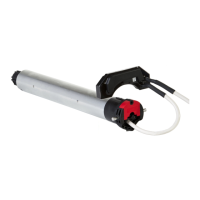
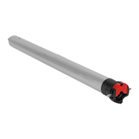
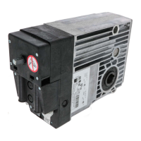
Tubular operators with integrated radio for blinds & roller shutters.
S.A.S. au capital de 5 000 000 € - Z.I. Les Giranaux - BP71 - 70103 Arc-Les-Gray CEDEX - RCS GRAY B 425 650 090 - SIRET 425 650 090 00011 - n° T.V.A CEE FR 87 425 650 090
Read carefully these instructions
before any use.
5010945D
GB
m
- We recommend that the power supply of each motor offers the possibility of being switched off individually.
- Drilling of the tube :
- Assembly :
- Do not position the transmitter near metal in order to avoid range losses.
230V-50Hz
Blue Brown Green / yellow
120V-60Hz
White Black Green
T5Hz.02
NL
PE
1
2
3
5
4
Ø4,8 x 10
Ø5 x 10
ACIER-STEEL-STAHL-ACERO-ACCIAIO
1 32 4
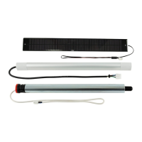
1 : Wall Hz ND transmitter
2 : Long-range Hz transmitter
3 : 1/5 channels Hz transmitter
4 : Hz timer
Transmitters range :
- 1, 3 and 4 : 20 m through 2 concrete walls .
- 2 : 40 m m through 2 concrete walls.
Location of the “PROG” key on Hz transmitters :
1/4
Wiring
2
m
- If the installation includes several motors, only one motor is to be powered during this
programming procedure. It will eliminate interferences with the other motor during the procedure.
m
The end-limit adjustement can be done in two ways:
- First you can memorize the DOWN position and then the UP position (stage 4.3.a).
- First you can memorize the UP position and then the DOWN position (stage 4.3.b).
2/4
4.1
- Switch ON the motor.
- Simultaneously press the UP and DOWN keys of a
Hz transmitter. The motor will run for half a
second in one direction, then the other.
The transmitter now controls the Hz.02
motor in unstable mode, move to stage 4.2.
>>
>>
3s
a OK
>>
>>
>> 4.3
>>
OK >> 4.3
b
4.2 - Checking the rotation direction
Press the UP key of the transmitter:
a- If the motorized tube runs in the UP direction , move to next stage (4.3).
b- If the motorized tube runs in the DOWN direction, reverse the rotation direction by pressing the STOP key for at
least 3 seconds. The motor will confirm the reversal of the rotation direction by running for half a second in one
direction, then in the other direction. Move to the stage 4.3.
1- Position the motor on the DOWN end limit by using the keys DOWN or UP.
2- To memorize the DOWN end limit position, press simultaneoulsy the keys STOP and UP. The motor will run
automatically in the UP direction.
3- When the motor arrives on the UP End limit, press the key STOP.
4- If necessary adjust the position with the keys UP or DOWN.
5- To memorize the UP end limit position, press simultaneoulsy the keys STOP and DOWN. The motor will run
automatically in the DOWN direction.
6- Press 2 seconds
the STOP key to validate the setting. The motor will stop, and will run for half a second in
one direction, then in the other direction.
4.3 - Adjustement of the end-limits : memorizing the end points
4.3.a
End limits adjustment
4
m
- Recommendations :
- Keep a minimum distance of 20 cm between two T5 Hz.02 motors. Keep a minimum distance of 30 cm between T5Hz.02 motors and Hz transmitters.
- A radio appliance using the same frequency (433,42MHz) may deteriorate our product’s performance (ex. : hi-fi radio headphones).
- The cable may only be connected to the motor by qualified personnel.
- The connector is to be assembled without damaging the contacts.
- The continuity of the earth connection must be ensured.
Installation
1