SINAMICS G120
Standard inverters 0.37 kW to 250 kW (0.5 hp to 400 hp)
Supplementary system components
Brake Relay
4/109
Siemens D 11.1 · 2009
4
■
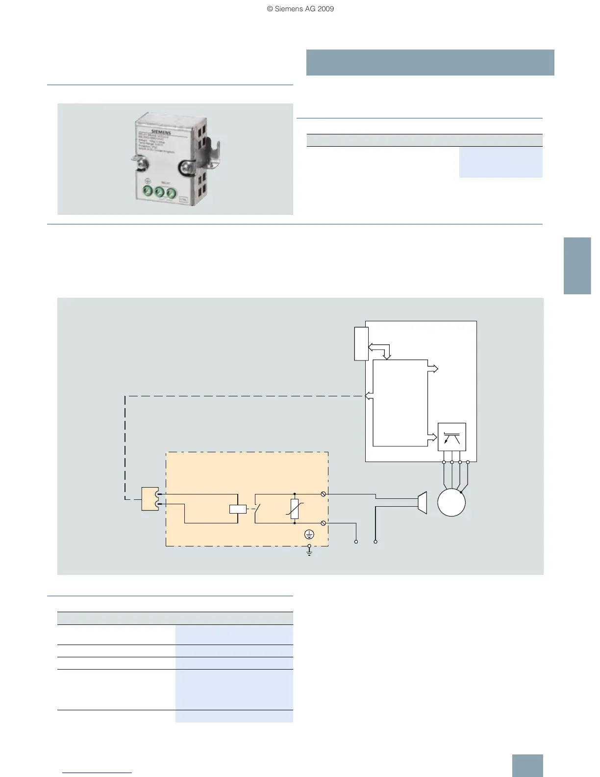
Overview
The Brake Relay allows the Power Module to be connected to an
electromechanical motor brake, thereby allowing the motor
brake to be driven directly by the Control Unit.
■
Selection and ordering data
■
Integration
The Brake Relay has the following interfaces:
• A switch contact (NO contact) to control the motor brake
solenoid
• A connection for the cable harness (CTRL) for connection to
the Power Module
The Brake Relay can be installed on the shield bonding plate
near the power terminals of the Power Module.
The supplied Brake Relay includes the cable harness for
connection with the Power Module.
Connection example of a Brake Relay
■
Technical specifications
Order No.
Brake Relay
Including cable harness for connection to the
Power Module
6SL3252-0BB00-0AA0
Brake Relay
CTRL
U2
V2
W2
PE
M
3 ~
Power
Module
G_D211_EN_00070
Voltage supply
motor brake
PM-IF interface
Cable harness
Brake Relay
Max. switching capability of the
NO contact
440 V AC / 3.5 A
30 V DC / 12 A
Max. conductor cross-section
2.5 mm
2
Degree of protection IP20
Dimensions
• Width 68 mm
•Height 63 mm
•Depth 33 mm
Weight, approx. 0.17 kg
 Loading...