SINAMICS G120
Standard inverters 0.37 kW to 250 kW (0.5 hp to 400 hp)
Supplementary system components
Safe Brake Relay
4/110
Siemens D 11.1 · 2009
4
■
Overview
The Safe Brake Relay allows the Power Module to be safely con-
nected to an electromechanical motor brake, allowing the brake
to be directly and safely controlled by the Control Unit in accor-
dance with EN 954-1 Safety Category 3 and IEC 61508 SIL 2.
■
Selection and ordering data
■
Integration
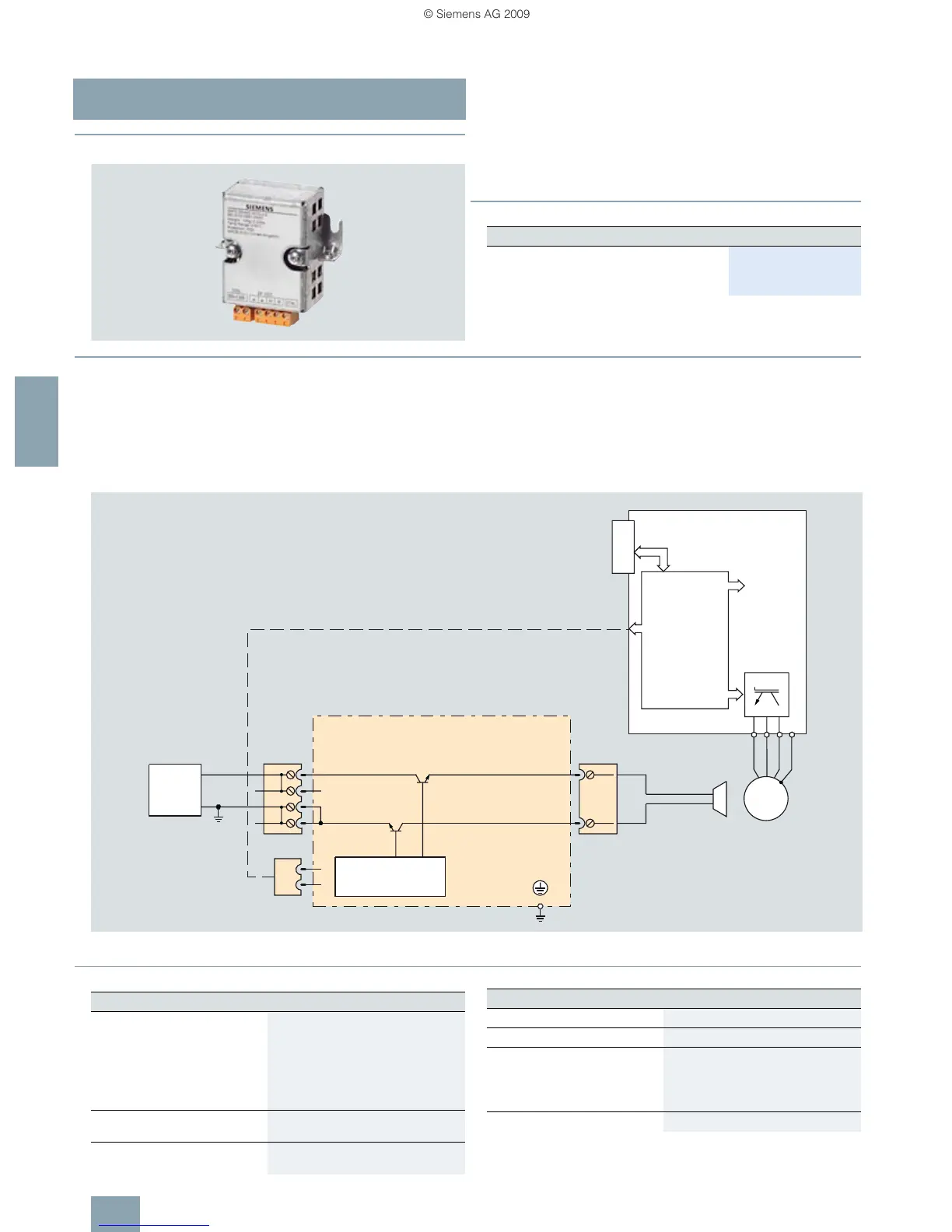
The Safe Brake Relay has the following interfaces:
• A two-channel transistor output stage to control the motor
brake solenoid
• A connection for a 24 V DC power supply
• A connection for the cable harness (CTRL) for connection to
the Power Module
The Safe Brake Relay can be mounted on the shield bonding
plate near the power terminals of the Power Module.
The supplied Safe Brake Relay includes the cable harness for
connection with the Power Module.
The 24 V DC solenoid of the motor brake is directly connected to
the Safe Brake Relay. External surge suppressors are not re-
quired.
Connection example of a Safe Brake Relay
■
Technical specifications
Order No.
Safe Brake Relay
Including cable harness for connection to the
Power Module
6SL3252-0BB01-0AA0
U2
V2
W2
PE
M
3 ~
Power
Module
Safe Brake Relay
CTRL
M
+
M
+
M
+
BR-
BR+
G_D211_EN_00071
ext.
24 V
PM-IF interface
Cable harness
Safe Brake Relay
Supply voltage 20.4 … 28.8 V DC
Recommended rated value of the
26 V DC supply voltage
(to equalize and compensate for the
voltage drop along the feeder cable
to the 24 V DC solenoid of the motor
brake)
Max. current requirement of
motor brake
2A
Current requirement at
24 V DC, max.
0.005 A + the current requirement of
motor brake
Max. conductor cross-section 2.5 mm
2
Degree of protection IP20
Dimensions
• Width 68 mm
•Height 63 mm
•Depth 33 mm
Weight, approx. 0.17 kg
Safe Brake Relay
 Loading...