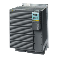
SINAMICS G120
Standard inverters 0.37 kW to 250 kW (0.5 hp to 400 hp)
PM250 Power Modules –
7.5 kW to 75 kW (10 hp to 100 hp)
4/58
Siemens D 11.1 · 2009
4
■
Technical specifications
Line supply voltage
380…480V3AC
PM250 Power Modules
Without integrated line filter 6SL3225-
0BE33-0UA0
6SL3225-
0BE33-7UA0
6SL3225-
0BE34-5UA0
6SL3225-
0BE35-5UA0
6SL3225-
0BE37-5UA0
With integrated line filter 6SL3225-
0BE33-0AA0
6SL3225-
0BE33-7AA0
6SL3225-
0BE34-5AA0
6SL3225-
0BE35-5AA0
6SL3225-
0BE37-5AA0
Output current at
50 Hz 400 V 3 AC
• Rated current I
rated
1)
A 75 90 110 145 178
• Base load current I
L
1)
A 75 90 110 145 178
• Base load current I
H
2)
A 60 75 90 110 145
• I
max
A 120 150 180 220 290
Rated power
• based on I
L
kW (hp) 37 (50) 45 (60) 55 (75) 75 (100) 90 (125)
• based on I
H
kW (hp) 30 (40) 37 (50) 45 (60) 55 (75) 75 (100)
Rated pulse frequency kHz 4 4 4 4 4
Efficiency
η
>0.97 >0.97 >0.97 >0.97 >0.97
Power loss
(at rated current)
kW 0.99 1.21 1.42 1.93 2.31
Cooling air requirement m
3
/s 0.022 0.039 0.094 0.094 0.117
Sound pressure level L
pA
(1 m)
dB <60 <62 <60 <60 <65
24 V DC power supply for
Control Unit
A 1 1 1 1 1
Input current
3)
• Rated current A 70 84 102 135 166
• based on I
H
A 56 70 84 102 135
Line supply connection
U1/L1, V1/L2, W1/L3
M6 screw studs M6 screw studs M8 screw studs M8 screw studs M8 screw studs
• Max. conductor cross-sect. mm
2
10 … 50 10 … 50 25 … 120 25 … 120 25 … 120
Motor connection
U2, V2, W2
M6 screw studs M6 screw studs M8 screw studs M8 screw studs M8 screw studs
• Max. conductor cross-sect. mm
2
10 … 50 10 … 50 25 … 120 25 … 120 25 … 120
PE connection On housing with
M6 screw
On housing with
M6 screw
On housing with
M8 screw
On housing with
M8 screw
On housing with
M8 screw
Motor cable length, max.
4)
• Shielded m 50 50 50 50 50
• Unshielded m 100 100 100 100 100
Degree of protection IP20 IP20 IP20 IP20 IP20
Dimensions
• Width mm 275 275 350 350 350
•Height
- without integrated line filter mm 499 499 634 634 634
- With integrated line filter mm 635 635 934 934 934
•Depth
- without Control Unit mm 204 204 316 316 316
- with Control Unit mm 260 260 372 372 372
Frame size FSE FSE FSF FSF FSF
Weight, approx.
• Without integrated line filter kg 14 14 35 35 35
• With integrated line filter kg 21 21 51 51 51
1)
The rated output current I
rated
and the base load current I
L
are based on
the duty cycle for light overload (LO).
2)
The base load current I
H
is based on the duty cycle for high overload (HO).
3)
The input current depends on the motor load and is valid for a line impe-
dance corresponding to u
K
= 1 %. The rated input currents apply for a
load at the rated power (based on I
rated
) – these current values are speci-
fied on the rating plate.
4)
Max motor cable length 25 m (shielded) for PM250 Power Modules with
integrated line filter to maintain the limit values of EN 61800-3 Category C2.
 Loading...