SINAMICS G120
Standard inverters 0.37 kW to 250 kW (0.5 hp to 400 hp)
Compact inverters
0.37 kW to 15 kW (0.5 hp to 20 hp)
4/73
Siemens D 11.1 · 2009
4
■
Overview
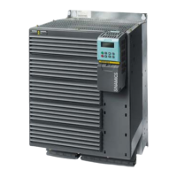
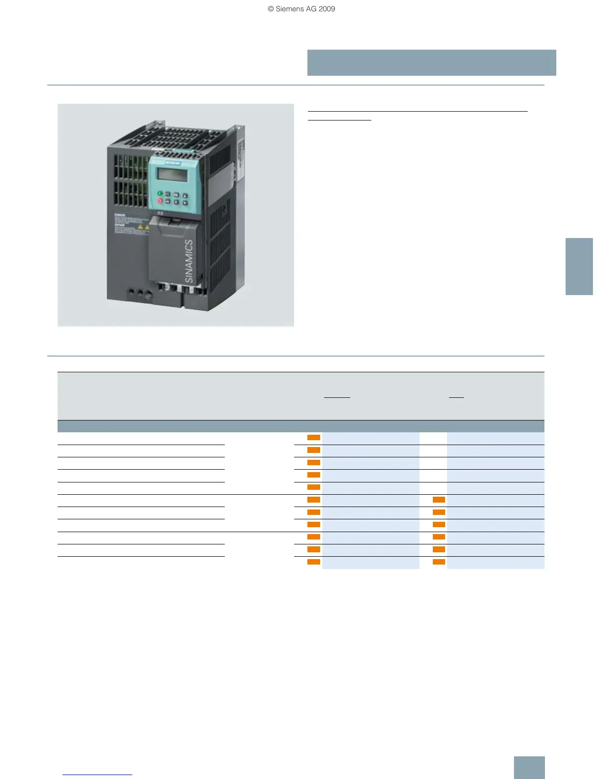
Example: Compact inverters, SINAMICS G120 with PM240 Power
Module frame size FSB, CU240E Control Unit and BOP
The entry into SINAMICS G120 with an already assembled
compact inverter
Three components can be ordered, completely assembled, with
one Order No.: The PM240 Power Module with integrated brake
choppers, the CU240E Control Unit and the BOP operator panel.
The compact inverter is suitable for applications in which the ad-
vantages of a compact inverter prevail (only one Order No., sim-
pler to order). In this case, the advantages of a consistently
modular system no longer apply (lower stockkeeping, high de-
gree of flexibility).
The individual components of the compact inverter still remain
completely modular. After they have been received, they can be
separated at any time.
■
Selection and ordering data
Rated power
1)
Power based on the
base load current I
H
2)
Frame size
and dimensions
(H × W × D)
SINAMICS G120
compact inverter
without integrated
line filter
SINAMICS G120
compact inverter
with integrated class A
line filter
kW hp kW hp mm Order No. Order No.
47 … 63 Hz 380 … 480 V 3 AC ±10 %
0.37 0.50 0.37 0.50 FSA
173 × 73 × 177
6SL3214-3AE13-7UB0 -
0.55 0.75 0.55 0.75 6SL3214-3AE15-5UB0 -
0.75 1.0 0.75 1.0 6SL3214-3AE17-5UB0 -
1.1 1.5 1.1 1.5 6SL3214-3AE21-1UB0 -
1.5 2.0 1.5 2.0 6SL3214-3AE21-5UB0 -
2.2 3.0 2.2 3.0 FSB
270 × 153 × 204
6SL3214-3AE22-2UB0 6SL3214-3AE22-2AB0
3.0 4.0 3.0 4.0 6SL3214-3AE23-0UB0 6SL3214-3AE23-0AB0
4.0 5.0 4.0 5.0
6SL3214-3AE24-0UB0 6SL3214-3AE24-0AB0
7.5 10 5.5 7.5 FSC
334 × 189 × 224
6SL3214-3AE25-5UB0 6SL3214-3AE25-5AB0
11.0 15 7.5 10 6SL3214-3AE27-5UB0 6SL3214-3AE27-5AB0
15.0 20 11.0 15 6SL3214-3AE31-1UB0 6SL3214-3AE31-1AB0
new
new
new
new
new
new new
new new
new new
new new
new new
new new
1)
Rated power based on the rated output current I
rated
.
The rated output current I
rated
is based on the duty cycle for light
overload (LO).
These current values are stamped on the rating plate of the Power Module.
2)
The base load current I
H
is based on the duty cycle for high overload (HO).
 Loading...