SINAMICS G120
Standard inverters 0.37 kW to 250 kW (0.5 hp to 400 hp)
DC link components
Braking Modules
4/86
Siemens D 11.1 · 2009
4
■
Overview
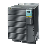
A Braking Module and the matching external braking resistor are
required to bring drives to a controlled standstill in the event of
a power failure (e.g. emergency retraction or EMERGENCY
STOP Category 1) or limit the DC link voltage for brief periods of
generator operation. The Braking Module includes the power
electronics and the associated control circuit. During operation,
the DC link energy is converted to heat loss in an external brak-
ing resistor. Braking Modules function autonomously.
The Braking Module is designed for installation in PM240 Power
Modules, frame size FSGX and is cooled by the Power Module
fan. The supply voltage for the electronics is taken from the DC
link. The Braking Module is connected to the DC link using the
busbar sets included in the scope of delivery.
The activation threshold of the Braking Module can be adjusted
by means of a DIP switch. The braking power values specified
in the technical specifications apply to the upper activation
threshold.
■
Selection and ordering data
■
Design
The Braking Module has the following interfaces as standard:
• 1 DC link connection
• 1 braking resistor connection
• 1 digital input (inhibit Braking Module/acknowledge fault)
• 1 digital output (Braking Module inhibited)
• 1 DIP switch for adjusting the activation threshold
■
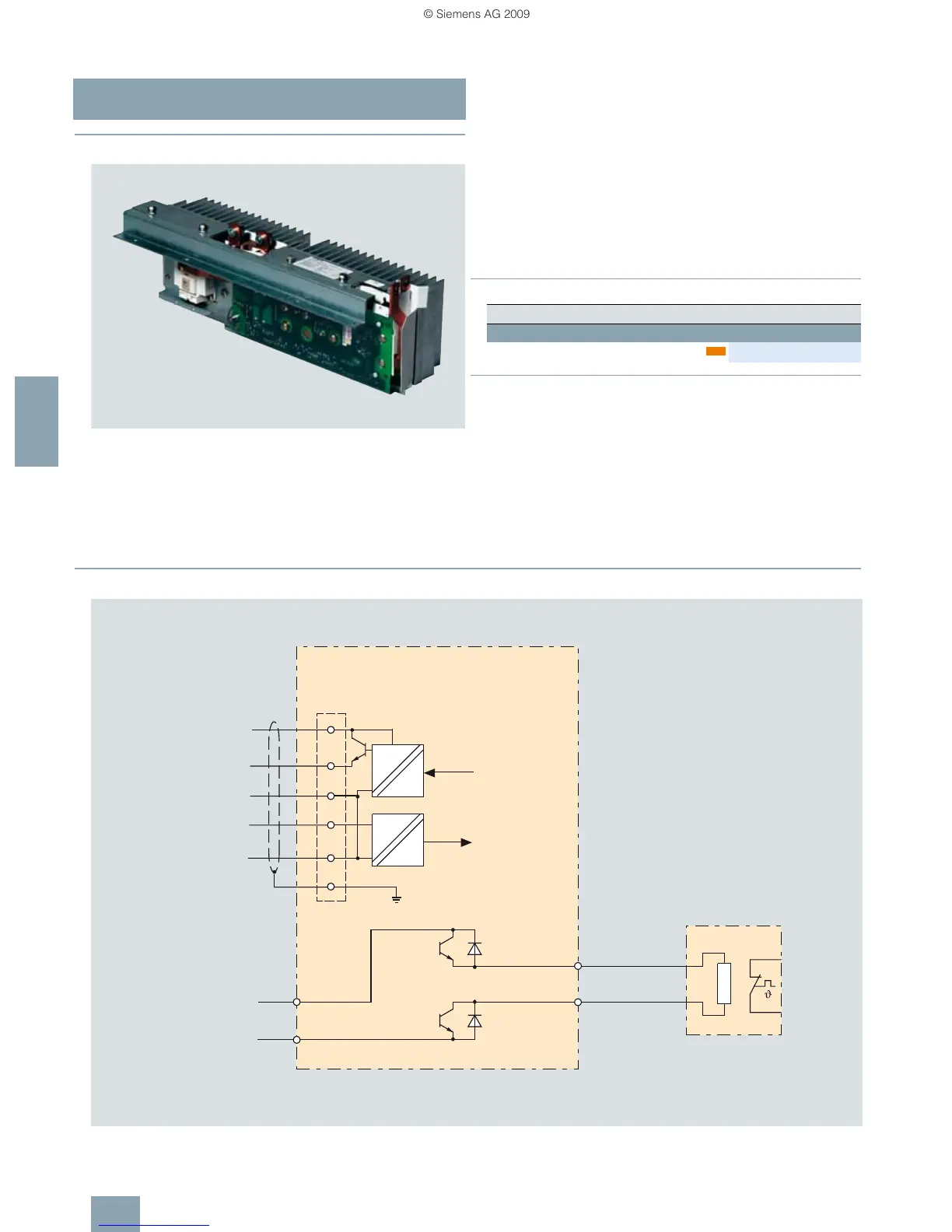
Integration
Connection example of a Braking Module
Description Order No.
DC link voltage 510 … 720 V DC
Braking Module 50 kW/250 kW 6SL3300-1AE32-5AA0
new
Braking Module
21.6
21.5
21.4
21.3
21.2
21.1
X21
+24 V
0 V
0 V
R1
DCNA
R2
DCPA
T1
T2
Fault
G_D211_EN_00012b
Connection to
DC link
Inhibit
Fault output
Inhibit input
Shield
Braking resistor
 Loading...