Sinclair MTV1 service manual V2.1 Page 18 of 39
Line and Fr
ame Oscillator and Drive
Composite sync from the video detector· is separated into line and frame sync. The line oscillator is
a phase locked loop with excellent hold in and pull-in. The frame oscillator is injection locked. Both
oscillators have excellent stability and are part of the third Sinclair designed bipolar linear
integrated circuits.
This device also includes the control circuit for the regulated EHT.
Oscillator-waveforms are fed to discrete transistor CRT deflection plate drive circuits.
The frame output is adjusted for the US 60Hz standard.
EHT Converter – 2kV
This is produced by a high efficiency switching convertor and is regulated.
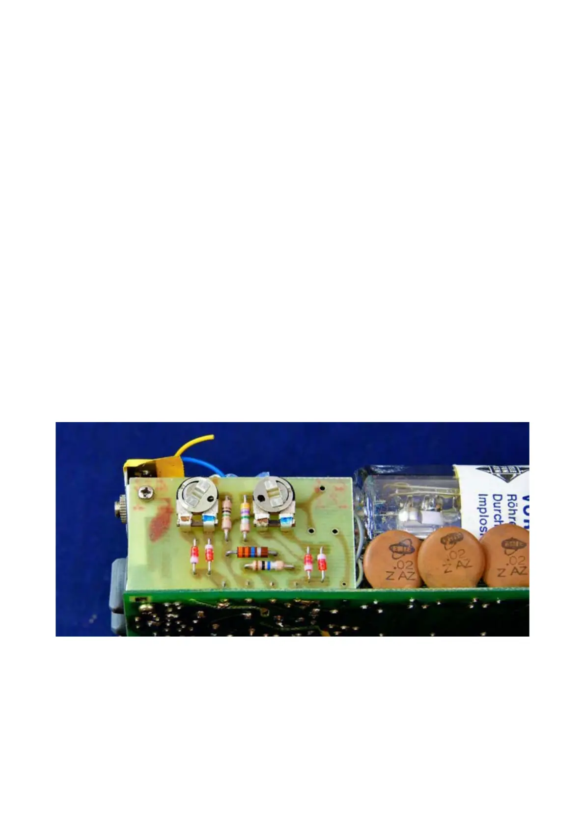
Line and frame shift board
The line shift and frame shift pots are contained on a small daughterboard permanently mounted to
the power board. Be aware that the pots are at high voltage and should only be adjusted with a
well-insulated tool.
As an asi
de, note the extremely high value resistors, of up to 33MΩ. Even higher values are
employed on the main board.