Sinclair MTV1 service manual V2.1 Page 4 of 39
TECHNI
CAL DESCRIPTION
System
The Sinclair Microvision MTV1 uses conventional television superheterodyne conversion to convert
RF signals into video. Intercarrier sound is taken off after video detection. All circuitry was designed
by Sinclair Radionics Ltd staff in England.
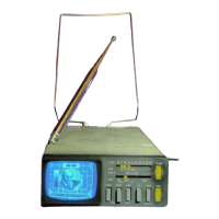
Power
The Microvision is powered by four internal nickel cadmium (Ni-Cd) 500mAh rechargeable cells
giving approximately 4 hours viewing time. The set can be recharged using the adaptors supplied
in about 14 hours. The set can also be powered by the mains adaptor/charger an external 6V
source, or an external 12V source eg automobile cigar lighter socket.
Dismantling Instructions
Remove the UHF aerial by unscrewing the two clips securing it to the inner aerial arms.
Remove the VHF aerial by pulling gently upwards vertically. Be very careful of the VHF aerial
plastic trim, which can easily be damaged. With sets now uniformly over 40 years old, the aerial
can be very reluctant to come out. It can be started by inserting something matchstick-size
between the bottom of the rod by the hinge and pressing the aerial rod down, thus levering its base
out of the socket. Once it has started moving it can normally be removed by straightening the hinge
and pulling the assembly by hand.
The aerial rod’s black plastic surround (where it enters the chassis) must be removed. Gently prise
it out, remembering that it was considered fragile even in 1977.
Remove the two screws from the back cover (over the controls) and remove this cover. Remove
the two screws to the external VHF aerial input and the 6V – 12V sliding cover.
Remove the two screws from the rear casing (above controls) and the two screws underneath the
case at the front. There are two more screws to remove, under the FCC label. The adhesive on the
label has become less effective with time. If the label is intact it is worth gently peeling it to reveal
the screw heads, rather than just shoving a screwdriver through the label.
The outer case will now slide back, leaving the chassis exposed. Remove the two screws from the
top and two from the bottom of the metalwork holding the front panel in place. In some models
there is a screw securing the audio board to this metalwork, which also has to be removed. This
panel and metalwork can now be slid forward.
The screws can now be removed from the rear of the tuner panel.