20
Handle
Front
side plate
To the power supply
To unit B
Power cord
To unit A
connecting
cable
L
connecting
cable
,1'22581,7$
$
,1'22581,7%
1
/
1
32:(5
/1
blue
blue
yellow-
green
yellow-
green
(black)
black
brown
brown
%
1
blue
yellow-
green
black
brown
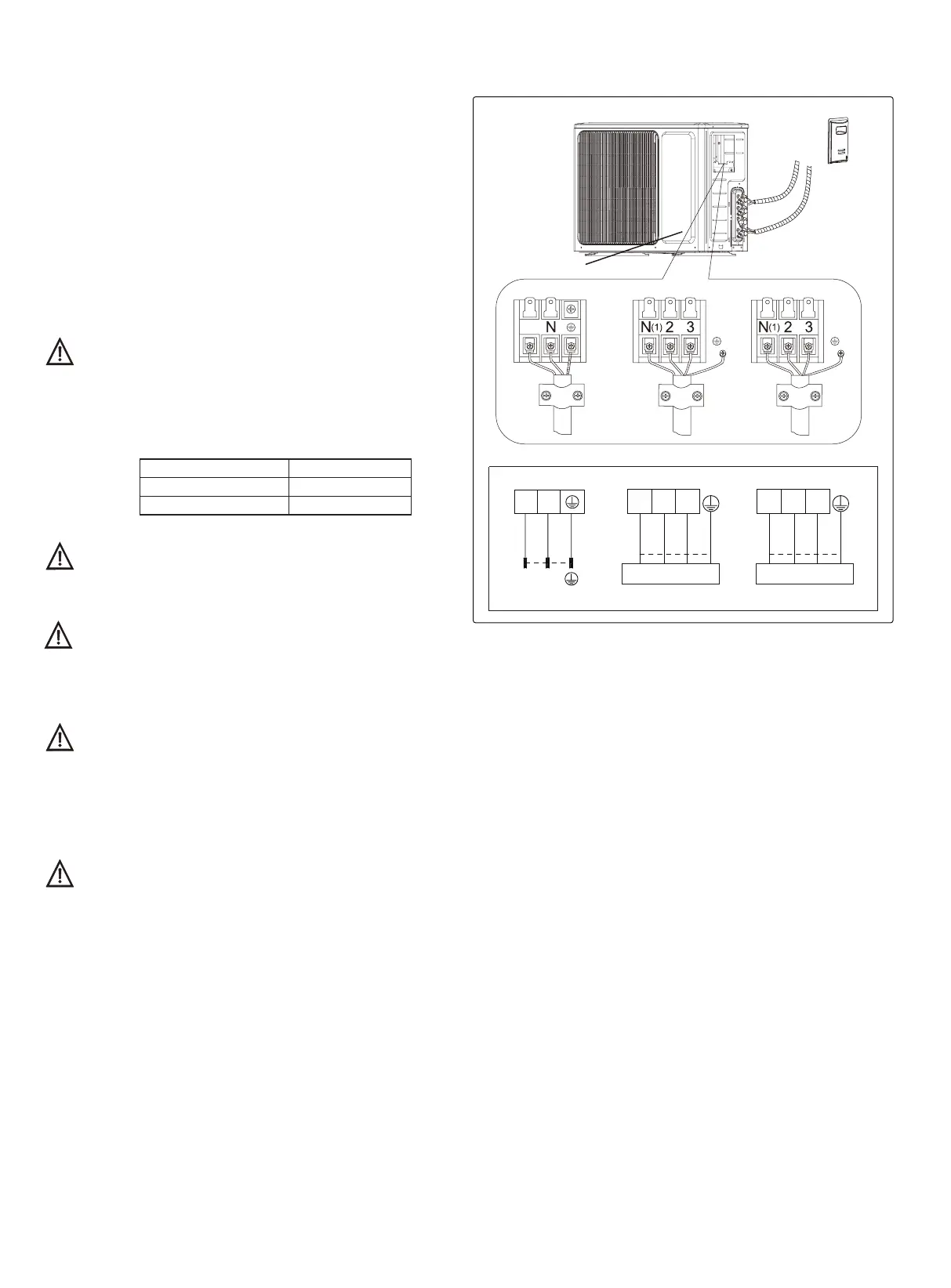
8.1 Electrical Connections
1. Remove the handle at the right side plate of the outdoor
unit (one screw).
2. Remove the cable clamp, connect the power connection
cable with the terminal at the row of connection and fix the
connection. The tting line distributing must be consistent with
the indoor unit. terminal of line bank. Wiring should meet that of
indoor unit.
3. Fix power connection wire by wire clamp.
4. Ensure wire has been xed well.
5. Install the handle.
Including an air switch with suitable capacity,please note
the following table. Air switch should be included magnet
buckle and heating buckle function, it can protect the
circuit-short and overload. (Caution: please do not use the
fuse only for protect the circuit)
Wrong wire connection may cause malfunction of
some electric components.After xing cable, ensure
that leads between connection to xed point have
some space.
An all-pole disconnection switch having a contact
separation of at least 3mm in all pole should be connected
in xed wiring.
The connection pipes and the connectiong wirings
of the unit A and unit B must be corresponding to
each other respective.
The appliance shall be installed in accordance with
national wiring regulations.
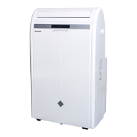
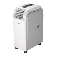
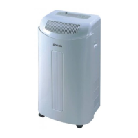
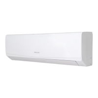
Note: the above gures are only intended to be a simple
diagram of the appliance and may not correspond to the
appearance of the units that have been purchased.
Air-conditioner Air switch capacity
14K 10A
18K
16A