26
14/18K: 24/28K:
43 Communication failure with Unit A
● Ƽ ● ●
44 Communication failure with Unit B Ƽ Ƽ ● ●
45 Communication failure with Unit C ○ ○ Ƽ ●
46 Communication failure with Unit D ● ○ Ƽ ●
47 Unit A freeze protection Ƽ ○ Ƽ ●
48 Unit B freeze protection ○ ● Ƽ ●
49 Unit C freeze protection ● ● Ƽ ●
50 Unit D freeze protection Ƽ ● Ƽ ●
51 Unit A overheating prevention protection ○ Ƽ Ƽ ●
52 Unit B overheating prevention protection ● Ƽ Ƽ ●
53 Unit C overheating prevention protection Ƽ Ƽ Ƽ ●
54 Unit D overheating prevention protection
○
○
○
Ƽ
55 Unit A communication wire misconnection or expansion valve malfunction ● ○ ○ Ƽ
56 Unit B communication wire misconnection or expansion valve malfunction Ƽ
○
○
Ƽ
57 Unit C communication wire misconnection or expansion valve malfunction ○ ● ○ Ƽ
58 Unit D communication wire misconnection or expansion valve malfunction ● ● ○ Ƽ
Note: discharge the position in below pictures with discharge resistance after open the top cover and
check if the voltage is below 20V with universal meter, then begin to check.
1 IPM protection malfunction:
Main checking point:
● If the input voltage of the unit is within normal range?
● If the connection wire of compressor is connected well? Is it loose? If the connection sequence is correct?
● If the resistance of compressor coil is normal? If the isolation of compressor coil with copper pipe is good?
● If the unit is overloaded? If the heat radiation of the unit is good?
● If the refrigerant charge is suitable?
Flow chart:
9.3 Malfunction Checking and Elimination
Compressor overload protection
Viewing malfunction code
through remote controller within
200s; displayed directly on
nixietube after 200s
H3
PL noitcnuflam erawdraH hctam ton od tinu roodtuo dna tinu roodnI
EE noitcnuflam erawdraH pihc yromem fo noitcnuflaM
Wrong connection of communication wire or malfunction of
electronic expansion valve
Hardware malfunction
dn
Malfunction of complete units current detection Hardware malfunction U5
3L noitcnuflam erawdraH 1 naf roodtuo fo noitcetorp noitcnuflaM
Detection status of wrong connection of communication wire
or malfunction of electronic expansion valve
Operation status
dd
7E sutats noitarepO tcilfnoc edoM
oF sutats noitarepO edom gnilcycer tnaregirfeR
LA sutats noitarepO naf-X
1H sutats noitarepO edom gnitaeh ni nruter lio ro gnitsorfeD
Start failure of compressor
Viewing malfunction code
through remote controller within
200s; displayed directly on
nixietube after 200s
Lc
4E rosserpmoc fo noitcetorp erutarepmet egrahcsid hgiH
Overload protection E8
5E noitcetorp tnerrucrevo tinu elohW
5P noitcetorp tnerruc esahp rosserpmoC
Compressor desynchronizing H7
dL noitcetorp esrevni-esahp/gnikcal-esahp rosserpmoC
IPM modular protection H5
DC bus-bar low volt LP noitcetorp ega
HP noitcetorp egatlov hgih rab-sub CD
PFC protection HC
7U lamronba si evlav yaw-ruof ehT
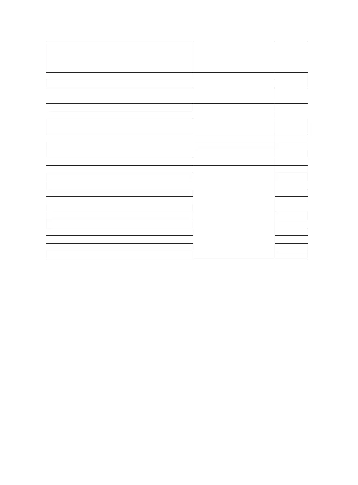
14/18K: 24/28K:
43 Communication failure with Unit A
● Ƽ ● ●
44 Communication failure with Unit B Ƽ Ƽ ● ●
45 Communication failure with Unit C ○ ○ Ƽ ●
46 Communication failure with Unit D ● ○ Ƽ ●
47 Unit A freeze protection Ƽ ○ Ƽ ●
48 Unit B freeze protection ○ ● Ƽ ●
49 Unit C freeze protection ● ● Ƽ ●
50 Unit D freeze protection Ƽ ● Ƽ ●
51 Unit A overheating prevention protection ○ Ƽ Ƽ ●
52 Unit B overheating prevention protection ● Ƽ Ƽ ●
53 Unit C overheating prevention protection Ƽ Ƽ Ƽ ●
54 Unit D overheating prevention protection
○
○
○
Ƽ
55 Unit A communication wire misconnection or expansion valve malfunction
●
○
○
Ƽ
56 Unit B communication wire misconnection or expansion valve malfunction Ƽ
○
○
Ƽ
57 Unit C communication wire misconnection or expansion valve malfunction ○ ● ○ Ƽ
58 Unit D communication wire misconnection or expansion valve malfunction ● ● ○ Ƽ
Note: discharge the position in below pictures with discharge resistance after open the top cover and
check if the voltage is below 20V with universal meter, then begin to check.
1 IPM protection malfunction:
Main checking point:
● If the input voltage of the unit is within normal range?
● If the connection wire of compressor is connected well? Is it loose? If the connection sequence is correct?
● If the resistance of compressor coil is normal? If the isolation of compressor coil with copper pipe is good?
● If the unit is overloaded? If the heat radiation of the unit is good?
● If the refrigerant charge is suitable?