6 SINCRO® is a brand of Soga Energy Team ITALY | sogaenergyteam.com | info.sincro@sogaenergyteam.com
INSTALLATION
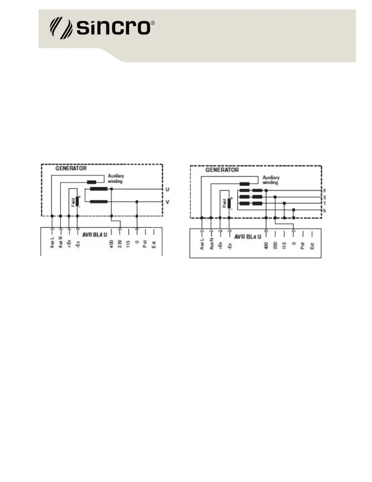
CONNECTION DIAGRAMS
The figures below show the connection for a alternator with a nominal line voltage of 1Ph 230 Vac
or 3Ph 400Vac. The sensing will be accomplished using the line voltage at input contacts named
400, 230, 115 and 0.
AVR BL4-U Connection diagrams: a) 1Ph - sensing 230V, b) 3Ph - sensing 400 V
CONNECTION TERMINALS
Sensing voltage
400, 0 = 400 Vac
230, 0 = 230 Vac
115, 0 = 115 Vac
Supply voltage
Aux L, AuxN
Alternator field
+Ex, -Ex
External adjustment potentiometer
Ext, Pot