REGOLAZIONE DELLA VELOCITA
La frequenza e la tensione dipendono diret-
tamente dalla velocità di rotazione, la quale
deve quindi rimanere il più possibile costan-
te al variare del carico.
Considerando che il sistema di regolazione
della velocità dei motori di trascinamento
presenta in generale una leggera caduta di
giri tra vuoto e carico, si raccomanda di
regolare la velocità a vuoto circa il 3÷4%
superiore alla velocità nominale.
SPEED ADJUSTMENT
Frequency and voltage depend directly on
the speed of revolution, which must therefore
remain as constant as possible when the
load varies.
The speed adjustment system of the drive
motors usually gives a slight drop in
revolutions between no load and load, so
when the no load speed is being adjusted, it
is best to set it at approx. 3-4% above the
rated speed.
RÉGLAGE DE LA VITESSE
La fréquence et la tension dépendent
directement de la vitesse de rotation qui doit
rester le plus possible constante quand la
charge varie.
Vu que le système de réglage de la vitesse
des moteurs dentraînement présente en
général une légère baisse du nombre de
tours à vide ou en charge, il est conseillé de
régler la vitesse à vide à une valeur
supérieure de 3 à 4% par rapport à la
vitesse nominale.
ISTRUZIONI PER IL MONTAGGIO
(FORMA IM B35)
ATTENZIONE: prima del montaggio verifi-
care che le sedi coniche di accoppiamento
(sia della saldatrice che del motore) siano
regolari e ben pulite.
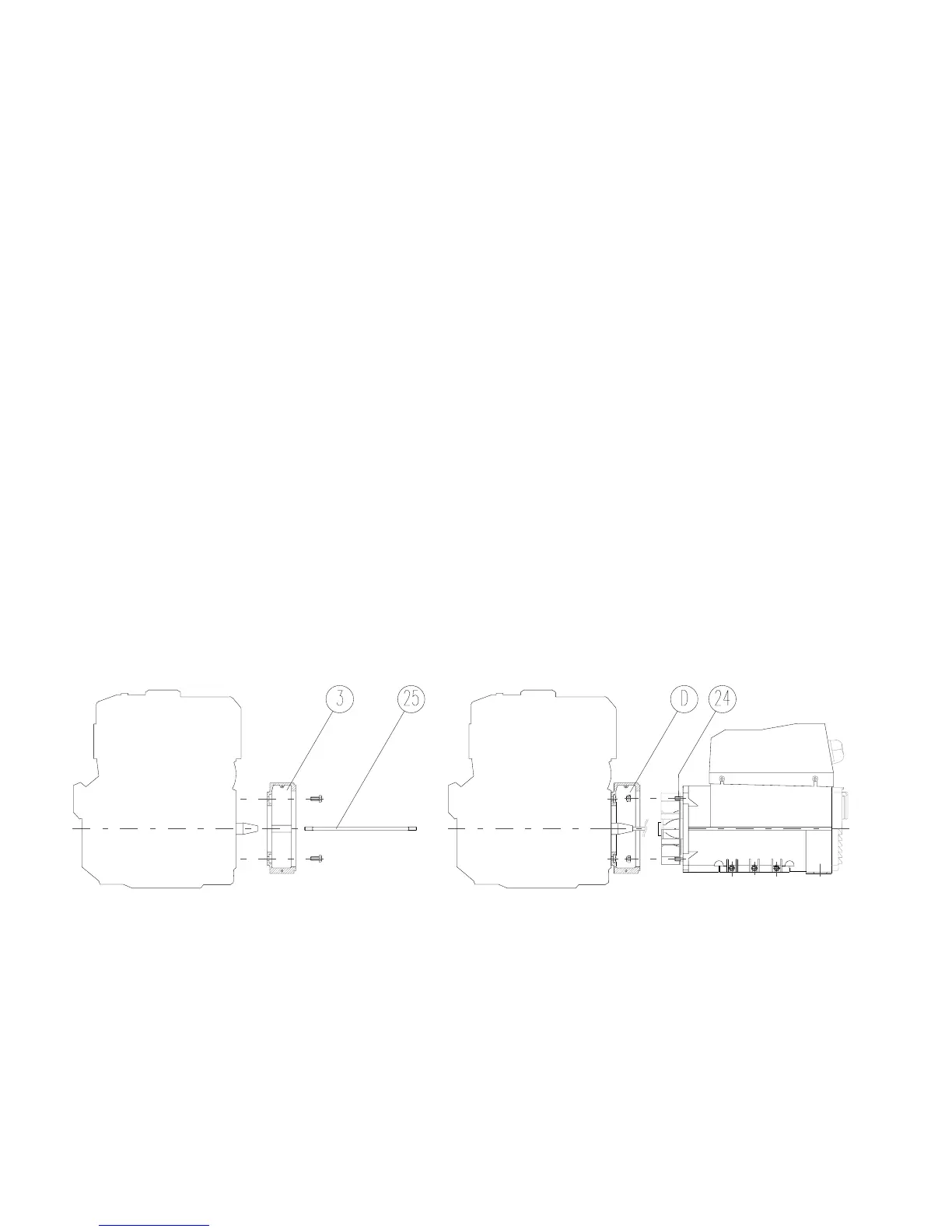
1) Fissare lo scudo copriventola (3) al
motore (dopo averlo tolto dalla
saldatrice).
2) Applicare il tirante (25) per il fissaggio
assiale del rotore avvitandolo sulla spor-
genza dellalbero motore.
3) Fissare la saldatrice completa (statore
e rotore assieme) allo scudo usando i 4
tiranti M8 (24) e i dadi autobloccanti M8 (D).
4) Bloccare assialmente il rotore avvitan-
do il dado autobloccante M8 (D) sul
tirante (25).
Attenzione: prima di applicare il dado osser-
vare che parte della porzione filettata del
tirante entri nel rotore permettendo cosí un
sicuro bloccaggio.
5) Montare il tappo (22). Fissare le due
griglie di protezione (1).
6) Supportare il gruppo con adeguati
antivibranti (A) curando il corretto alli-
neamento tra motore e saldatrice.
ASSEMBLY INSTRUCTIONS
(IM B35 COUPLING)
ATTENTION: before assembly make sure
that the conical coupling housings for both
the welding machine and the motor are in
order and clean.
1) Clamp the fan shield (3) on the drive
motor (after removing it from the weld-
ing machine).
2) Apply the tie rod (25) for the axial
clamping of the rotor, and screw it on
the drive shaft.
3) Fasten the complete welding machine
(stator and rotor together) to its shield,
using the 4 tie rods M8 (24) and the M8
(D) self-locking nuts.
4) Axially lock the rotor in place by tight-
ening the M8 (D) self-locking nut on the
tie rod (25).
Caution: before applying the nut, make sure
that the threaded part of the rod partially
enters the rotor in order to obtain tight lock-
ing.
5) Fit the cap (22). Fasten the two protec-
tion grids (1).
6) Support the unit on appropriate vibra-
tion dampers (A) ensuring that the
motor and the welding machine are
correctly aligned.
INSTRUCTIONS POUR LE MONTAGE
(FORME IM B35)
ATTENTION: Avant deffectuer le montage,
vérifier que les sièges coniques daccou-
plement (de la soudeuse comme du mo-
teur) sont en ordre et bien nettoyés.
1) Fixer le bouclier couvre-rotor (3) au
moteur (après lavoir désolidarisé de
la soudeuse).
2) Mettre en place la tige (25) de fixation
axiale du rotor en la vissant à lergot de
larbre moteur.
3) Fixer la soudeuse (complète avec sta-
tor et rotor) au bouclier au moyen de 4
tiges M8 (24) et les écrous
autobloquants M8 (D).
4) Bloquer laxe du rotor en serrant lécrou
autobloquant M8 (D) sur la tige cen-
trale (25).
Attention: Avant de mettre en place lécrou,
contrôler que la partie filetée de la tige est
insérée dans le rotor permettant ainsi un
blocage sûr.
5) Fixer le bouchon (22). Fixer les deux
grilles de protection (1).
6) Soutenir le groupe avec des amortis-
seurs de vibrations (A) en faisant at-
tention que le moteur et la soudeuse
soient dans le même axe.
MONTAGEANLEITUNG
(IMB35 ANSCHLUSS)
 Loading...