Revised April 28, 2010
12850-87
Avenue
Surrey, BC. Canada. V3W 3H9
Ph: 604-594-5404
Fx: 604-594-8845
www.singervalve.com
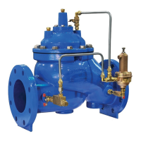
MODEL S106/S206-PG POWER OPERATED GLOBE VALVE
Sizes 6” to 16" (S106-PG) 12” to 24" (S206-PG)
Installation, Operating and Maintenance Instructions
DESCRIPTION:
This valve is the basic component used for most
Singer Automatic Valves. It is a hydraulically
operated valve.
DESCRIPTION OF OPERATION:
The valve opens when the bonnet (area above the
diaphragm) is connected to the downstream side of
the valve AND a pressure drop of 5 psi (35 kPa) is
available across the valve. The valve also opens
when the bonnet is vented to atmosphere, regardless
of pressure drop, provided that the line pressure is 5
psi (35 kPa) or more.
The valve closes when the inlet pressure is directed to
the bonnet.
The valve can be made to modulate by varying the
bonnet pressure between inlet pressure and outlet
pressure. This is done by the pilot circuit.
In some cases the line media is unsuitable for use in
the pilot system. In these circumstances external
water pressure can be used in the pilot system. The
external pressure must be equal to or higher than the
line pressure.
Unless otherwise specified, the valve is assembled
with components suitable for water service up to
180
o
F (80
o
C). For other service conditions, contact
your Singer Valve representative.
STORAGE:
This valve must be stored indoors, away from
direct sunlight.
INSTALLATION:
Use washers under nuts when bolting valve
flanges to pipe flanges to protect the Epoxy
Coating.
Control valves must be installed in a horizontal pipe
with the bonnet up. Smaller valves (6” and smaller)
can be installed in a vertical pipe if the order states
the orientation. Disassembly is difficult but not
impossible in valves installed in vertical pipe.
A stable, non-failing source of pressure is necessary
to operate a pilot operated control valve.
Operating fluid must be clean and free of air.
Under high velocity conditions the pressure signal,
when the pick-up point is located on the main valve
inlet, may be adversely affected. As an example, a
relief valve will operate more effectively and control
more accurately if the operating pressure and sensing
pressure is connected to the header.
Ideally, six pipe diameters of straight pipe is required
on the inlet of any control valve but
• Fully open Gate Valve can be installed on the
inlet of a valve, provided it is used as an isolating
valve and never used in partially open condition.
• A Butterfly Valve with stem horizontal can not
be
installed in the inlet of a control valve unless
operating pressure and sensing lines are
connected upstream of the butterfly valve, in a
location that gives true system pressure.
• A Butterfly Valve with stem vertical can be
installed in the inlet of a control valve as long as
velocity does not exceed 15 ft/sec. The butterfly
valve can not be used for throttling. If problems
develop at high flows, operating pressure and
possible sensing can be connected upstream of
the butterfly valve, in a location that gives true
system pressure.
• A control valve can be installed with no straight
pipe on the inlet if the operating and sensing lines
are connected to a location that gives true system
pressure.
The connection point should be made at the pipe
centerline to avoid air pick-up at the top of the pipe.
1. It is possible that diaphragms may take a set
after shipping and storage. It is highly
recommended that Bonnet and Body Bolts or
Nuts be tightened after installation but before
pressurizing the valve. If a leak develops after
pressurizing, de-pressurize the valve and
tighten the bolts or nuts.
IOM 224C Page 1 of 2 August 2007
 Loading...