EasyManua.ls Logo

Singer 101 Series - Page 14

Singer 101 Series
20 pages
Print Icon
To Next Page IconTo Next Page
To Previous Page IconTo Previous Page
Loading...
To Set the
Needle
Bar
at the Correct
is centred
on the top
of the finger
of the timing
gauge (V2, Fig.
20)
on the upward
stroke
of
the needle bar.
When the needle
bar
connecting
stud
(U2) is in
this position,
the needle bar
should be
set so
that the top
of the eye
of the
needle will be about
inch
below
the point
of the hook
as shown at
“X2” in Fig.
20.
In
case the
needle
bar is not set at
the correct
height, loosen
the screw
in the lower
end of
the needle bar connecting
link
(T2, Fig.
19, page
21). (This
screw can be reached
when the
needle
bar is at its
lowest point
by inserting
a screwdriver through
the hole
provided
for the
purpose in
the arm). After loosening
the screw,
move
the needle
bar up or
down in the
needle bar con-
necting stud
(U2, Fig. 20)
until
it is at the correct
height, as
instructed
above, then
firmly
tighten the screw
in the needle bar
connecting
link.
To
Remove
and Replace
the Sewing
Hook
To remove
the hook,
take
out the centre screw
(W2, Fig. 19,
page 21) which
holds
the hook
to the hook
shaft and
lift
out the
hook.
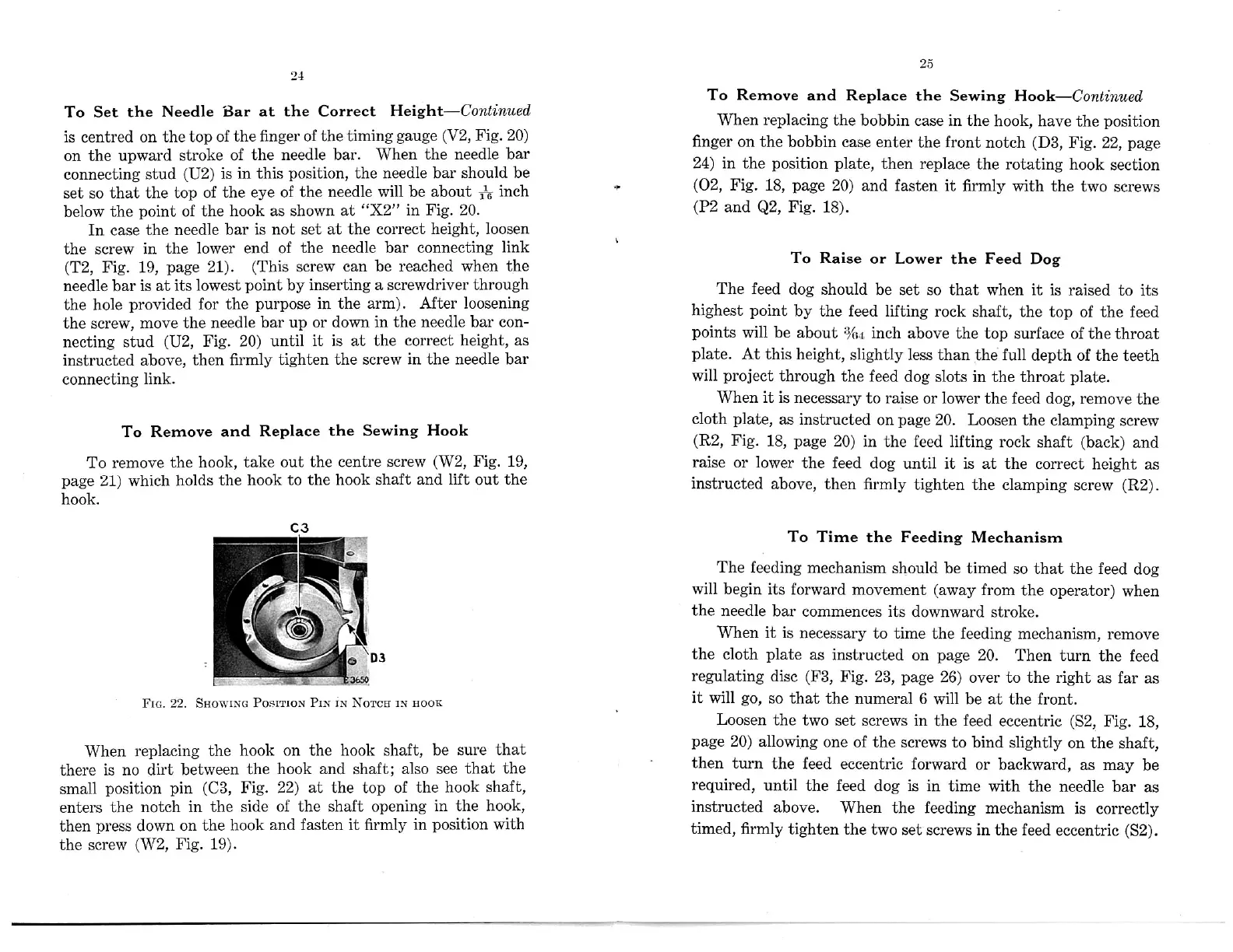
FIG. 22.
POSITION PIN IN IN HOOK
When
replacing
the hook
on the hook shaft,
be sure that
there
is no
dirt between
the
hook and shaft;
also see that
the
small
position
pin
(C3, Fig.
22) at the top of
the hook
shaft,
enters the
notch in
the side
of the shaft opening
in the hook,
then press
down on
the hook
and fasten it firmly
in position
with
the
screw
(W2,
Fig. 19).
25
To Remove
and Replace
the Sewing
When
replacing
the bobbin
case in the
hook, have the
position
finger
on the bobbin
case enter
the front notch
(D3, Fig.
22, page
24) in the position
plate, then replace
the
rotating hook
section
(02, Fig.
18, page 20) and
fasten it firmly
with the
two screws
(P2 and Q2, Fig. 18).
To
Raise or
Lower the Feed
Dog
The feed
dog should
be set
so that when it is
raised to its
highest
point
by the
feed lifting rock
shaft, the top
Of the feed
points will
be about
inch
above
the top surface
of the throat
plate.
At this height,
slightly less
than the full
depth of the
teeth
will project
through
the feed dog
slots in the throat
plate.
When it is necessary
to raise
or lower the
feed dog, remove
the
cloth plate,
as instructed
on
page 20. Loosen
the clamping screw
(R2,
Fig. 18, page
20) in
the feed lifting rock
shaft
(back) and
raise or lower
the feed
dog until
it is at the correct
height as
instructed
above,
then firmly
tighten the clamping
screw
(R2).
To Time the Feeding
Mechanism
The
feeding mechanism
should be timed
so that the
feed dog
will begin
its forward
movement
(away from
the operator)
when
the
needle bar
commences its
downward
stroke.
When it
is necessary
to time
the feeding mechanism,
remove
the
cloth plate
as instructed
on page
20. Then
turn the
feed
regulating
disc
(F3, Fig.
23, page
26) over to the right
as
far as
it will
go, so
that the
numeral 6 will
be at the
front.
Loosen
the
two set
screws in the feed
eccentric
(S2, Fig. 18,
page 20)
allowing
one of the
screws to bind
slightly on
the shaft,
then turn the
feed eccentric
forward
or backward,
as may
be
required,
until the
feed dog
is in time with
the needle
bar
as
instructed
above.
When
the feeding
mechanism
is correctly
timed, firmly
tighten
the two
set screws in the
feed eccentric
(S2).
24
Height—Continued
11—5
SHOWING
NOTCH
Hook—Continued
"Aer