- 18 -
4. When oil wick leaders are correctly installed, replace holder screw H3,
Fig. 25.
5. Adjust the three oil wick loops in holder (see Figs. 24 and 25), so that
two of the loops come as close as possible to, without touching, the two
sets of needle bearings B3 while the third wick loop makes positive contact
with the wick inside the stud Y2, in the needle bar link, as shown in
Fig. 24.
6. Securely tighten holder screw H3.
7. Replace arm plug screw J3.
8. Replace upper section of presser bar, upper needle bar bushing and needle
bar, as instructed on pages 13 and 14.
9. Replace face plate, as instructed on page 2.
REMOVAL (See Figs. 28 to 30)
1. Remove the face plate.
2. Remove the arm side shield and wick and the thread take-up oil guard, as
instructed on pages 16 and 17.
3. Remove the needle bar, upper needle bar bushing, presser foot and presser
bar, as instructed on pages 13 and 14.
4. Remove entire thread take-up lever assembly, as instructed on pages 14 and 15.
5. Loosen the four screws in the arm top cover and remove the arm top cover.
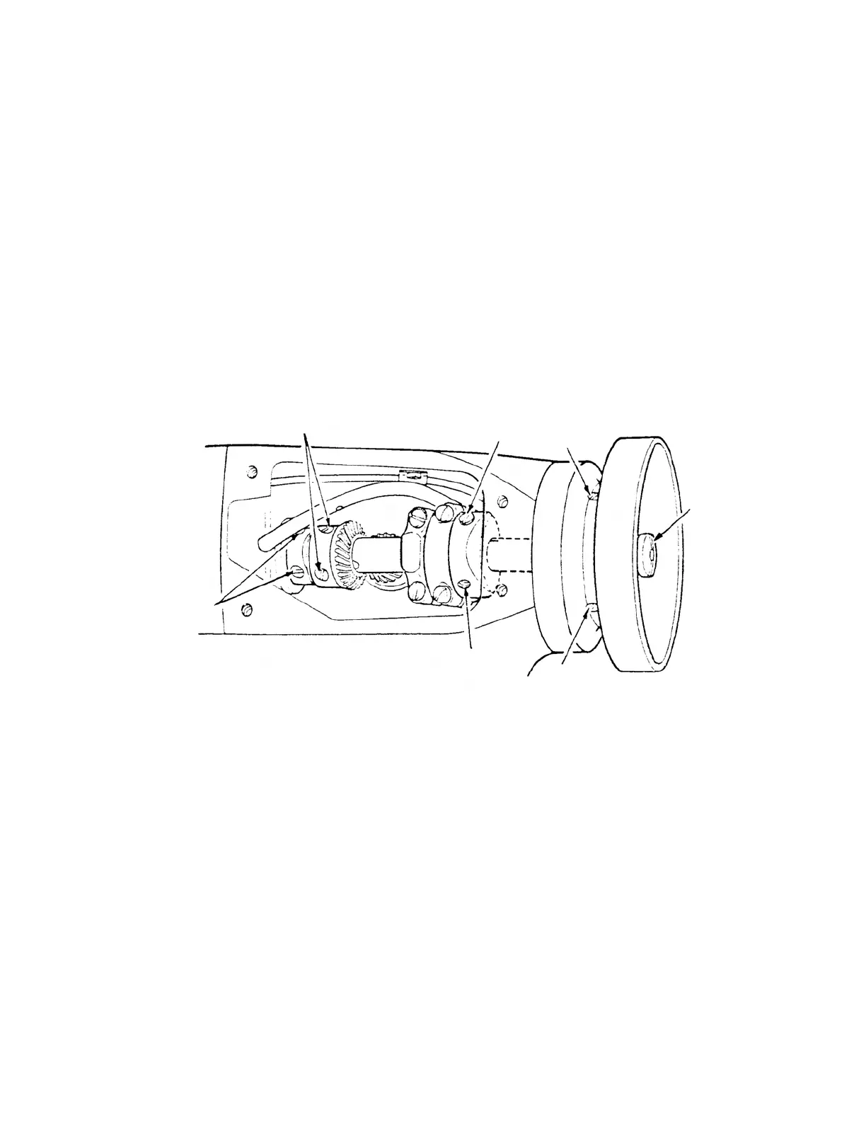
6. Remove the feed timing screw M, Fig. 28 and loosen the set screw N, Fig. 28
in the feed and feed lifting eccentric.
7. Loosen the two set screws P3 in the bevel gear and the two set screws Q3 in
the thrust collar.
8. Remove arm shaft screw R3, Fig. 28 from machine pulley end of arm shaft.
THE ARM SHAFT
Fig. 28
N
S3
R3
S3
M
P3
Q3