50
Removal:
Replacement:
1-
1-
1
116 117
1
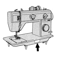
Remove the free arm extension table, tension assembly dial, the knobs of the zig-zag and needle
position levers and all covers (face plate, rear, bottom bed and front).
2- Remove retaining ring (S), the cam controlled feed follower (O) and the retaining ring located
under it.
3- Remove link screw (P) through the pattern selector dial hole.
4- Remove needle position selection lever assembly (Q).
Replacement is the same as removal but in reverse order.
2- Check and adjust if necessary:
Left-center-right needle position. (Pages 70-7 )
Disc and disc follower clearance. (Pages 58-59)
Cam stack radial play (Pages 58-59)
Needle bar pendulum timing. (Pages 66-67)
Buttonhole cutting space. (Pages - )
Needle location left-to-right (Pages 70-7 )
Zig-zag bight stop positioning (Pages 76 to 79)
l
l
l
l
l
l
l
Needle position selector lever
P/N 357773-002
Service Manual
MAY/00
Rev. n .
o
 Loading...