Bobbin Winder Replacement & Adjustment: (continued)
wrapped around the underneath part. Note that some of these units will
hav
don
9.
10.
art will insert itself into the center post of the bobbin
11. read is wrapped lint
12.
13.
17.
19.
ow.
20. th
w.
e
ak
ed a
g
s
it
ill
is r
ll add the Bobbin Winder document that was provided as a standalone
document, at the end of this manual. Go ahead and return the Hook Removal Section, next page, bullet 11.
Clean the unit all up, and ensure no threads are
e a little plastic washer, don’t loose it, and don’t damage it during cleaning. Others may not, so if yours doesn’t,
’t worry about it.
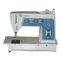
We want to inspect the thread cut off, and ensure it isn’t
broken, or damaged. Yellow arrow, Fig 1. It should
appear as shown. Now I don’t know of a way to sharpen
it, and ideally it is pretty much maintenance free.
We also want to inspect the driver tab that engages the
bobbin. Yellow arrow, Fig 2. Just ensure it isn’t
broken, or has been bent downward. Generally, it
should just fine. Also inspect the bobbin-centering pin.
Yellow circle. Ensure it hasn’t been flattened out. This
1
p
when winding.
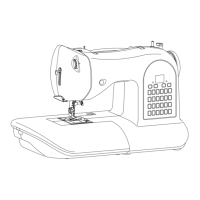
As mentioned before bullet 9, ensure no th
stuck inside the hook area. Fig 3,
yellow arrows.
Go ahead and clean up the other
bobbin winder parts. Then inspect for
thread underneath the hook. If you
need to remove the hook, go ahead and
around the shaft, and you don’t have any thread, or
3
skip to that section, and we’ll return to
this part for installing the hook driver.
Note before you install the hook
driver, that it only fits back into the
machine two ways, but only one is
correct. And that is with it seated
down as far as it’ll go. Note the items
shown by the blue arrows, it fits this
way correctly.
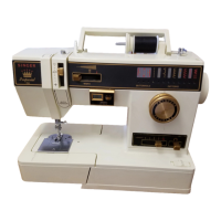
14. Reinstall the spring, item 23
15. Reinstall the positioner, item 25. Do
not that the hook driver has a notched
area that this part must fit onto
properly before tightening up the nut.
16. Reinstall item 22
Reinstall item 21, the lock nut. Don’t
wrench it down, just good and snug.
18. Ensure the unit moves up and down
freely. Do this by pushing up on item
22, where the lift cam, item 19, or
19A would fit.
Reinstall item 17, or 17A. Also
ensure the part is broken, or have any
cracks in the plastic. If so, replace it n
Reinstall item 19, or 19A. Also ensure
e it no
e part is broken, or have any
The crack is most noticeable
stment will not remain
r failure. Just install the lift
e contact with item 22.
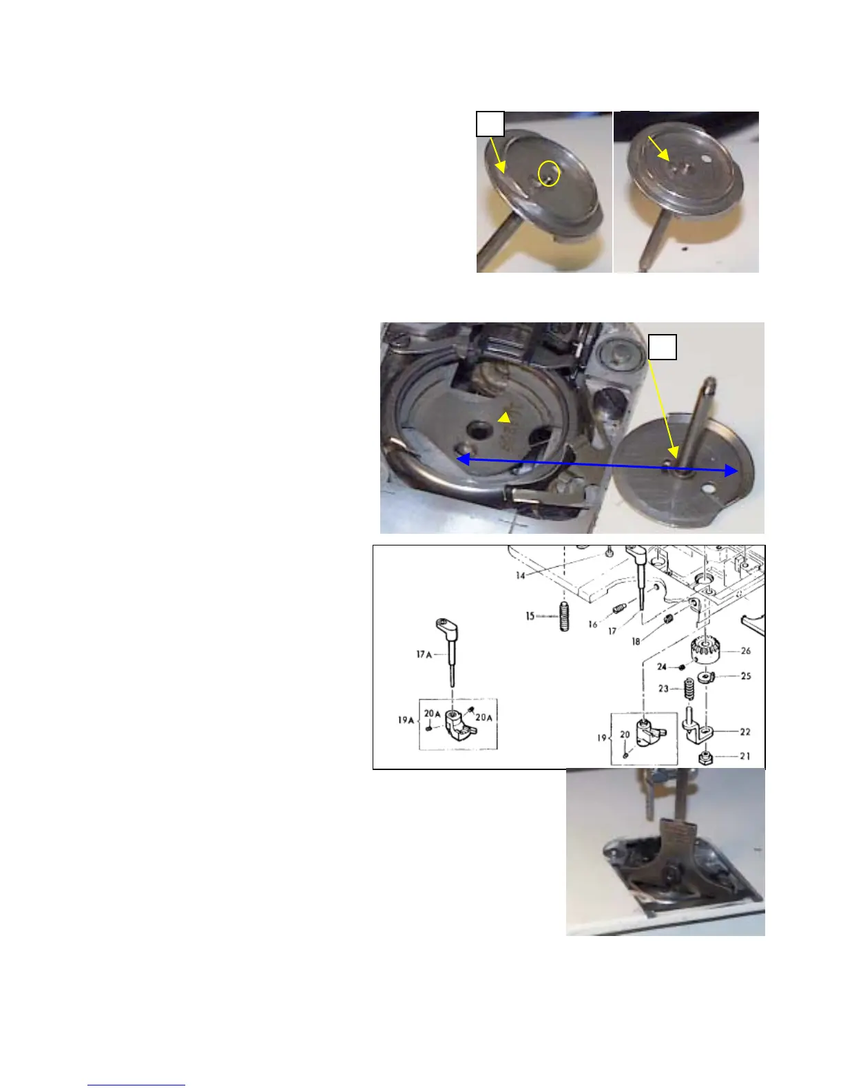
depth gauge here. Lets adjust
you’ll have to repeat it a few
e to approximately 5/64 to
shown, and activate the lever.
h the depth gauge. Adjust until
it correct, and all the parts are in good condition, along with either a good
wind correctly at the point. The depth gauge has to lay flat across the
from a 600, on the 700, you’ll need to position the gauge across the othe
cracks in the plastic. If so, replac
in the plastic sleeve. If it is cracked, adju
accurate, and you will have bobbin wind
cam on the lever, until it just starts to m
21. Now for the tricky part, and you do ne
for proper lift height, and more than likely
times before it is right. Set the depth gau
3/16 of an inch. Place the depth gauge a
The hook drive will just make contact w
you achieve the proper lift. If you have
bobbin, or new bobbin – preferred, it w
surface of the hook. The picture shown
way, by the lever and thread pull off. I’
 Loading...