SET
SCREWSv
—
::Vr.-'
M
" ,
p.
ROTARY
SHAFT
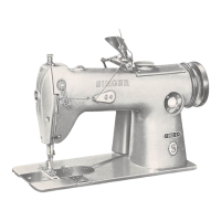
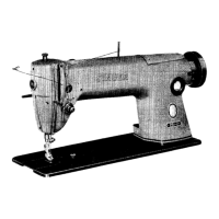
Fig.
28.
Timing
the
Loopers
BEVEL
GEAR
—"v-A
"r3
W-
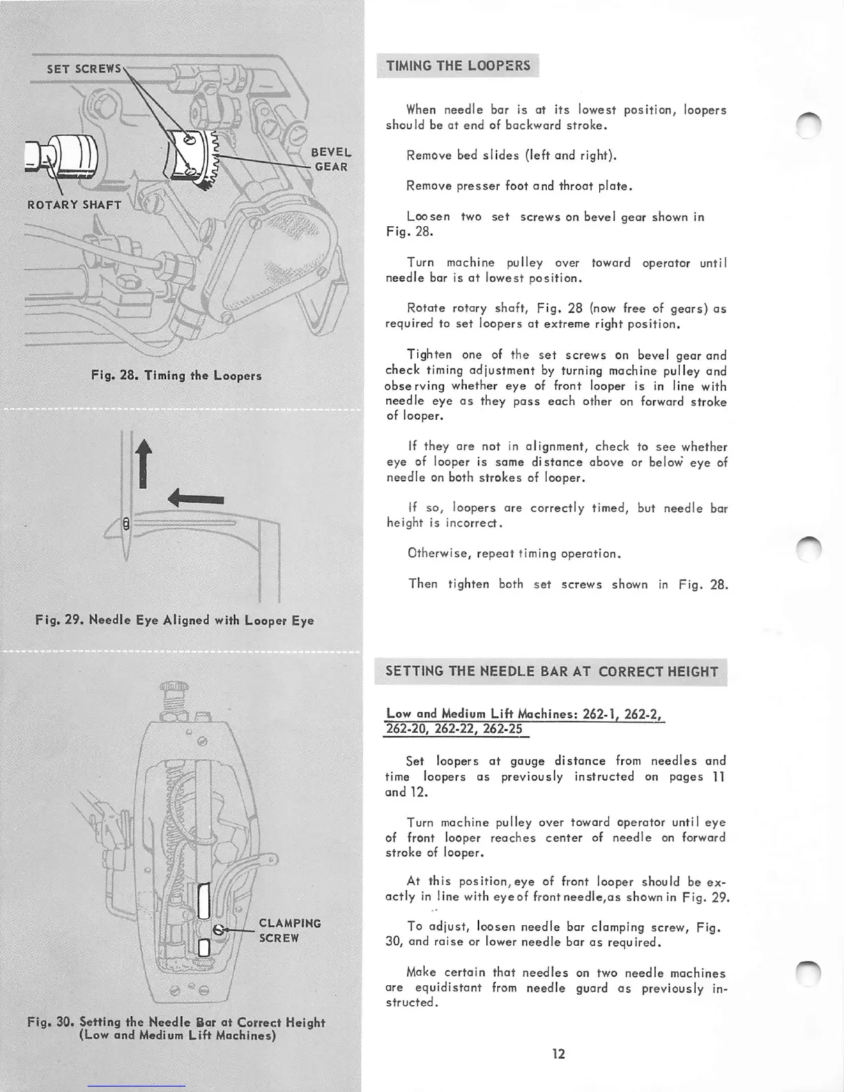
Fig. 29. Needle Eye Aligned with Looper Eye
' /
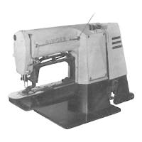
CLAMPING
\ f //
SCREW
Fig. 30. Setting
the
Needle Bor
at
Correct Height
(Low and
Medium
Lift Machines)
TIMING
THE
LOOPERS
When
needle bar is at its lowest position, loopers
should
be
at
end
of
backward
stroke.
Remove bed
slides
(left and right).
Remove
presser
foot and throat
plate.
Loosen two
set
screws on bevel gear shown in
Fig.
28.
Turn machine pulley over toward operator until
needle bar is at lowest position.
Rotate rotary shaft, Fig, 28
(now
free of gears) as
required to
set
loopers at extreme right position.
Tighten one of the
set
screws on bevel gear and
check timing adjustment by turning machine pulley and
observing
whether
eye
of front looper is in line with
needle eye as they pass each other on forward stroke
of looper.
If they ore not in alignment, check to
see
whether
eye of looper is some
distorKre
above or below eye of
needle on both
strokes
of looper.
if so, loopers are correctly timed, but needle bar
height is incorrect.
Otherwise, repeat timing operation.
Then tighten both set screws shown in Fig. 28.
SETTING
THE
NEEDLE
BAR
AT
CORRECT
HEIGHT
Low
and
Medium
Lift
Machines:
262-1,
262-2,
262-20,
262-22,
262-25
Set loopers at gouge
distance
from needles and
time loopers as previously instructed on pages 11
and
12.
Turn machine pulley over toward operator until
eye
of front looper
reaches
center
of needle on forward
stroke of looper.
At
this
position,eye
of front looper should be ex
actly in line with eyeof front needle,as shown in Fig. 29.
To adjust, loosen needle bar clamping screw. Fig.
30, and raise or lower needle bar as required.
Make
certain
that
needles
on two
needle
machines
are equidistant
from
needle
guard
as previously in
structed.