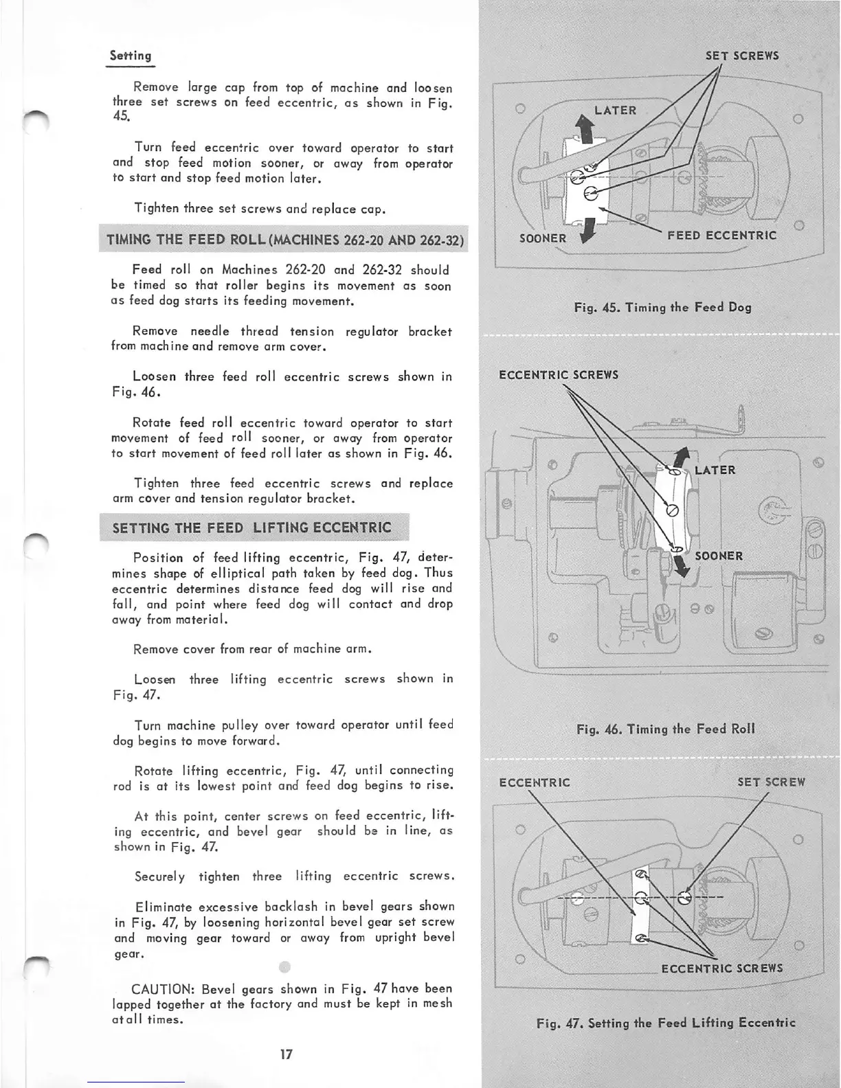
Setting
Remove
large cop
from
top of mochine and loosen
three set screws on feed eccentric, as shown in Fig.
45.
Turn feed eccentric over toward operator to start
and stop feed
motion
sooner, or
away
from
operator
to
start
and
stop
feed motion
later.
Tighten three set screws and replace cap.
TIMING
THE FEED
ROLL
(MACHINES
262-20
AND
262-32)
Feed
roll
on
Machines
262-20
and
262-32
should
be timed so that roller begins
its
movement as soon
as
feed dog
starts
its
feeding movement.
Remove
needle thread tension regulator bracket
from
machine
and
remove
arm
cover.
Loosen
three
feed
roll
eccentric
screws
shown
In
Fig.
46.
Rotate feed roll eccentric toward operator to start
movement
of feed roll sooner, or away
from
operator
to
start
movement of feed roll later as shown In
Fig.
46.
Tighten three feed eccentric screws and replace
arm cover and tension regulator bracket.
SETTING
THE
FEED
LIFTING
ECCENTRIC
Position of feed lifting eccentric, Fig. 47, deter
mines shape of elliptical path taken by feed dog. Thus
eccentric
determines dlstarKre feed dog will
rise
and
fall, and point where feed dog will contact and drop
away
from
material.
Remove
cover
from
rear
of
machine
arm.
Loosen three lifting eccentric screws shown in
Fig.
47.
Turn machine pulley over toward operator until feed
dog begins to move forward.
Rotate lifting eccentric. Fig. 47, until connecting
rod is at
its
lowest point and feed dog begins to
rise.
At this point, center screws on feed eccentric, lift
ing eccentric, and bevel gear should be in line, as
shown in
Fig.
47.
Securely tighten three lifting eccentric screws.
Eliminate
excessive
backlash
in bevel
gears
shown
in Fig. 47,
by
loosening horizontal bevel gear set screw
and
moving
gear toward or away
from
upright bevel
CAUTION:
Bevel gears shown in Fig. 47 have been
lapped together at the factory and must be kept in mesh
atoll
times.
SET
SCREWS
LATER
fTP"
SOONER
FEED
ECCENTRtG
Fig. 45. Timing
the
Feed
Dog
ECCENTRIC
SCREWS
vx#
LATER
Jr^
I h i
SOONER
Fig. 46. Timing
the
Feed
RoU
SET
SCR
ECCENTRIC
I
"T,
/
^5^
ECCENTRIC
SCREWS
Fig. 47. Setting the Feed Lifting Eccentric