. }J
CLAMP
W
SCREWS
M
\
\<^/^
:
\Yl^
SET
SCREWS
AVOIDING
ECCENTRIC
CRANK
ECCENTRIC
EDGE
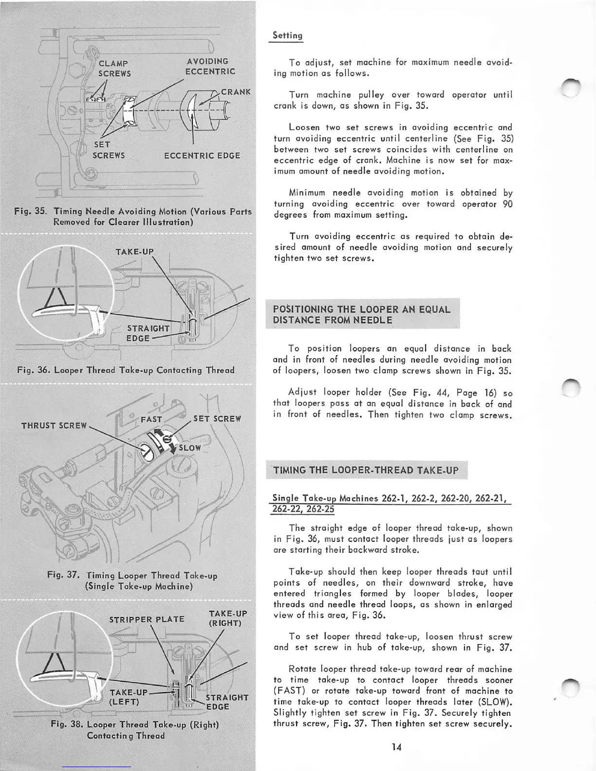
Fig.
35. Timing Needle Avoiding Motion (Various
Ports
Removed
for
Clearer
Illustration)
TAKE-UP
'4
om.
iv:vxA\avrfvan
/ t
STRAIGHT
iiu.
• i /
Fig.
36. Looper Thread Take-up Contacting Thread
ft S-FAST-^-^^.SET
SCREW
THRUST
SCREW
V.
/
^ I l • \
Fig. 37. Timing Looper Thread Take-up
(Single Toke-up Machine)
STRIPPER
PLATE
JfiGHVT
\ ^i
TAKE-UP.
(LEFT)
STRAIGHT
'EDGE
Fig. 38. Looper Thread Take-up (Right)
Contactin
g
Thread
Setting
To adjust, set machine for
maximum
needle avoid
ing motion
as
follows.
Turn machine pulley over toward operator until
crank
is down,
as
shown in
pig.
35.
Loosen two
set
screws
in avoiding
eccentric
and
turn avoiding
eccentric
until
centerline
(See
Fig.
35)
between
two
set
screws
coincides
with
centerline
on
eccentric
edge of crank. Machine is now
set
for max
imum amount of
needle
avoiding motion.
Minimum
needle avoiding motion is obtained by
turning
avoiding
eccentric
over toward
operator
90
degrees
from
maximum
setting.
Turn avoiding
eccentric
as
required to obtain de
sired amount of needle avoiding motion and securely
tighten two
set
screws.
POSITIONING THE
LOOPER
AN EQUAL
DISTANCE
FROM
NEEDLE
To position loopers an equal
distance
in back
and in front of needles during needle avoiding motion
of loopers, loosen two clamp screws shown in Fig. 35.
Adjust looper holder (See Fig. 44, Page
16)
so
that
loopers
pass
at
an equal
distance
in back of and
in front of needles. Then tighten two
clamp
screws.
TIMING
THE
LOOPER-THREAD
TAKE-UP
Single
Take-up
Machines 262-1, 262-2, 262-20, 262-21,
262-22,
262-25
The
straight edge of looper thread take-up, shown
in Fig. 36, must contact looper threads just
as
loopers
are starting
their
backward stroke.
Take-up should then keep looper
threads
taut
until
points
of
needles,
on
their
downward stroke, have
entered triangles formed by looper blades, looper
threads and needle thread loops, as shown in enlarged
view of thi s
area.
Fig.
36.
To
set
looper thread take-up, loosen
thrust
screw
and
set
screw in hub of take-up, shown in Fig. 37.
Rotate looper thread take-up toward rear of machine
to time take-up to
contact
looper
threads
sooner
(FAST) or rotate take-up toward front of machine to
time take-up to
contact
looper
threads
later
(SLOW).
Slightly tighten
set
screw in Fig. 37. Securely tighten
thrust screw. Fig. 37. Then tighten
set
screw securely.