Do you have a question about the sinmag LBC LCR5 and is the answer not in the manual?
Notes regarding unit shipment, stacking, installation, startup, and training.
List of available optional parts and accessories for the rotisserie ovens.
Details on mounting the rotisserie on countertops or floors using legs or casters.
Describes mounting the rotisserie on a dedicated stand, including specific stand models.
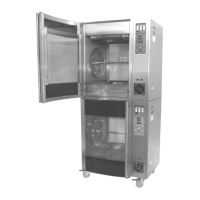
Information on stacking multiple rotisseries or a rotisserie with a holding cabinet.
Key duties of the owner/operator for installation, permits, site prep, utilities, and ventilation.
Instructions for checking for damage and loss upon delivery of the appliance.
Guidance on moving the appliance to its intended location before unpacking.
Steps for safely removing the appliance from its shipping materials and pallet.
Minimum required clearances from combustible construction and for servicing.
Information on attaching legs, casters, or a stand to the appliance.
Instructions for securely stacking multiple units or a unit with a holding cabinet.
How to unpack and install optional skewers and baskets.
Instructions for placing drip plates at the bottom of the oven cook chamber.
Details on connecting the appliance to electrical power, including conduit and flexible cord use.
Procedure for securing the unit to a building structure using the provided safety tether.
Pre-operation checks including door, packing materials, shipping ties, and cleaning.
Verifying controller functions and appliance states upon initial power-up.
Verifying the loading door switch functionality during preheating.
Testing the carousel rotation using the jog button when the door is open.
Confirming that the interior lights illuminate when the start/stop button is pressed.
How to switch the temperature display between Fahrenheit and Celsius.
Procedure for calibrating the oven's temperature controller using a thermocouple.
Using arrow buttons to scroll through and display recipes (1-20).
Programming up to three events (sear, roast, warm hold) for recipes.
Operating the timer functions: start, stop, and reset.
Using the jog button to rotate the carousel when the loading door is open.
Accessing frequently used recipes directly via dedicated buttons.
Saving a newly created recipe by pressing the save button twice.
Navigating back one event during recipe execution.
Switching the temperature display between Fahrenheit and Celsius.
Important warnings and cautions regarding electrical safety and using authorized replacement parts.
The main control unit for the rotisserie oven.
The assembly that holds the spits or baskets for rotation.
Wheels for moving the appliance.
Components responsible for generating heat within the oven.
Capacitors used in the fan motor circuit.
Sensor used to measure the internal temperature of the oven.
Electrical switches used to control various functions.
The motor that drives the carousel rotation.
Mechanism that transfers power from the motor to the carousel.
Fans located at the ceiling for air circulation.
The blades attached to the ceiling fans.
Switch that detects if the oven door is open or closed.
Internal lighting components for viewing the cooking process.
Parts related to the oven's loading door, including handles and inner/outer sections.
Specific heating elements (kW) for 5-Spit and 7-Spit configurations.
Capacitor used in the motor circuit.
Temperature-sensitive switches used for protection.
List and details of optional items like stands, spits, baskets, and kits.
Various types of angle spits available as accessories.
Various types of fork spits available as accessories.
Various types of baskets available as accessories.
Accessory kit for securing the appliance to a structure.
Specifications for the main motor used in the appliance.
Component of the motor brake assembly.
Solenoid component for the motor brake.
Hardware and procedures for attaching the motor to the gearbox.
Diagram showing the main power input and high voltage components.
Diagram illustrating the low voltage control wiring and components.
Table detailing heating element part numbers, kW ratings, and voltage for different models.
Table showing load, MCA, and MOP values for LCR5 and LCR7 models.
Detailed wiring for the main control board and associated components.
Wiring related to the switches that control cooking and washing modes.
Wiring diagram for the carousel rotation motor.
Wiring connections for the appliance's alarm system.
Details on what the warranty covers, including parts, labor, and service.
The duration of the warranty for parts and labor.
Requirements for the warranty to be valid, including installation and usage.
List of items and situations not covered by the warranty.