Do you have a question about the sinmag LBC LMO Max-E and is the answer not in the manual?
Critical safety precautions and warnings for operating the equipment.
Further warnings regarding electrical hazards, cleaning, and safe operation practices.
Step-by-step guide for lighting the oven, including daily and long-term shutdown.
Instructions for safely turning off the oven for daily use and long-term storage.
Guidelines for clearances, flooring, and assembly for electric oven installation.
Specifies acceptable parameters for water used in the electric oven.
Details electrical and water connection requirements for the electric oven.
Guidelines for clearances, flooring, and assembly for gas oven installation.
Specifies acceptable parameters for water used in the gas oven.
Details gas, electrical, and water connection requirements for the gas oven.
Outlines manufacturer's, owner's, and user's responsibilities for safe operation and maintenance.
Instructions for safe handling of heavy appliances and reporting any visible or concealed damage.
Covers electrical grounding, assembly, clearances, and specific gas oven requirements.
Detailed steps for safely uncrating, moving, and preparing the oven for installation.
Guides for setting oven in place, electrical, gas, water, and drain connections.
Specifics for water supply, drain connections, and hood ventilation interface.
Information on gas pressure settings and burner orifice differences for conversion.
Step-by-step instructions for changing orifices and restrictor plates for fuel conversion.
Final steps for completing the fuel conversion, including leak checks and lighting.
Checklist for initial installation quality, functional checks, and final inspection.
Specific tests for burner, combustion, steam, and sensor voltage readings.
Final checks on doors, gas, electrical, water, and contact information for support.
Diagram and settings for adjusting air opening gaps on the pressure panel.
Identifies and explains the functions of buttons and displays on the control panel.
Details settings like set-back, idle delay, illumination, and programming limitations.
Covers steam settings, power options, temp offset, and how to adjust parameters.
Table listing default values for oven control parameters like set-back and steam.
A section for general remarks or additional information not covered elsewhere.
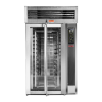
Identification of major oven parts and components of the top trim.
Breakdown of top trim components and parts within the upper front control box.
Identification of water supply line components and door closure mechanisms.
Breakdown of loading door components and light assembly parts.
Identification of rotation assembly components and blower motor/fan parts.
Parts for the electrical control box and the heater element.
Components of the gas oven control box and the heat exchanger assembly.
Identification of burner assembly, gas supply, igniter, and in-shot burner parts.
Comprehensive table listing part numbers for various oven components from 1 to 92.
Comprehensive table listing part numbers for various oven components from 100 to 207.
Schematic illustrating the high voltage power distribution and components.
Schematic detailing the low voltage control circuits and components.
Schematic for electric heat circuits for 208/240V and 480V 3-Phase ovens.
Schematic illustrating the gas heat circuit, including ignitor and flame sensor.
Details what the warranty covers, eligibility, and required installation/usage conditions.
Lists items and conditions not covered by the LBC limited warranty.
| Model | LBC LMO Max-E |
|---|---|
| Brand | Sinmag |
| Timer | Yes |
| Steam Injection | Yes |
| Weight | 85 kg |
| Power Supply | 50/60Hz |
| Temperature Range | 300°C |