24-25
2.2
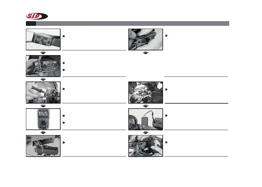
WIRING INSTRUCTION OF AC/DC MODELS
STEP 1
Open the original head light switch cover
STEP 7
Connect the black wire to the
head light’s ground. Alternatively to
the chassis or the engine.
STEP 8
Connect the power wire to
the meter’s power wires.
STEP 9
Connect the cable to the meter
and then fix the meter.
STEP 2
Start the engine, then use the multimeter
to identify the power wire.
Put the positive pole of the multimeter (red)
on the point under the “horn”
STEP 3
Put the negative pole of the
multimeter. (black) on the head
light engative pole.
STEP 5
Get the red and brown wires
out through the handle bar.
STEP 4
Adjust the unit on the multimeter
to AC, and the top voltage limit to 20V.
Then voltage should be measured as
AC10.5~12.5V
STEP 6
Connect the red and brown wires with
the original power wires.
1. Alternative connection option DC models: Black (DC):
Ground wire connect to chassis or engine; Red (DC):
positive pole,connect to battery; Brown (DC): connect
to permanent not switched power supply. Check possible
overvoltage!
2. Alternative connection option AC models: Black
(AC): Ground wire connect to chassis or engine;Red
(AC): connect to permanent not switched power supply.
Brown (AC): use the same connecting point as used for
the power pole.
 Loading...