Setting Up
Your compressor arrives assembled and works tested, ready for installation and
connection to your mains supply. On some models wheel mounting kits are
supplied, follow the instructions supplied with the wheel kit.
FOUNDATIONS:
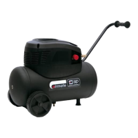
Direct Drive air compressors are supplied either with rubber feet
or wheel mounted. The feet and wheel absorb vibration; the compressor must not
be fixed rigidly to the floor and should be positioned on firm level ground.
SITING AND VENTILATION:
Good access and headroom should be provided
around the compressor for servicing. Adequate protection from the weather must
also be provided. Good ventilation is vital, for maximum efficiency. Intake air
should be as clean as possible. Air impurities, abrasive dust and corrosive gases
are particularly harmful to the compressor.
MAINS CONNECTION:
The compressor should be located as close to the mains
supply as possible. Check that this supply is the same voltage as marked on the
motor rating plate and that the wiring conforms in all respects to local regulations.
VOLTAGE DROP:
If the compressor is moved a long way from the mains supply, the motor may
appear to be sluggish, slow, buzz or unable to start. This is due to VOLTAGE
DROP caused by the extended lead to the compressor. This can be prevented,
by increasing the size of the cable. Incorrect voltage at the motor will invalidate
any guarantee.
BEFORE STARTING CHECK:
That the compressor is correctly installed and that the supply voltage is correct
and all fuses are correctly rated and intact. Also, that all maintenance checks
have been carried out and the contents of this manual have been read and fully
understood, by all appropriate persons.
PRESSURE SWITCH STARTER BUTTON:
Most machines are fitted with a black pressure switch combining a STOP/START
button on the top. In the 'UP' position the motor will start, in the 'DOWN' position
the motor will stop and the switch will bleed the pump head. If it is necessary to
stop the machine before the normal cut - out pressure is reached this button
should be depressed to stop it. NB: Some models may have a rotary switch
instead of a push button.
The Tn1.5/25-O models have a red rocker switch this if for STOP/START an
internal port performs the bleed function.
 Loading...