i
:
:
'
'
r------------------------------------------------
1
f
~~fm!U1&~JJJfjg
SAFETY SWITCH AND ITS FUNCTION
.-----------------------------------------------------------------------------
'
'
:
'
'
!
i
'
2.
~11Ji\
a:~fiHS(UT534K)
:
f.m~~J~t~&l'~
~t
~
w
7J
~
mfi
I1J
o
(~o
~
r-t
111
?ff
iJ\)
b.~tiHS(UT218J)
:
f.m~ffiU.t.~mli~
~
~~-2-!JJ
o
(~O~f-!:IIPffiJ\)
C.'~{iHJI(UT776)
:
~~ffiUL.~mti~tl.J~
~tfij21ii1J
o
(
~D~f~
j;iPJfiJ\)
3.
~~~~~f.m~)~
IJ
~t~&l'~~t~tlJ~~
~·~tm~-~~@~~~·tm~~~
~D*tt~,.S~
•
Jiffii¥~~5~~Q(IIJ7)
o
):£~:
( 1
)?'£
3~Hi
~
fiH
itJI
~
~
~
•
~~
lii~a%
rDJ
~~)m!!mll
'~~)m!~ll*llr-!1
P~
•
~~5±~~tif*I§&~§i~IHi~
IJ.ffimfiH§~~~~~~il~aB=
~(~O~f~I1PffiJ\)
o
~IE~
1. Pneumatic
a.
Solenoid valve (left side)1: is used to control
the presser foot
lift
and lower movement.
b.
Solenoid valve (middle)2:
is
used to control the
operation of the lower trimmer. (Including
needle
thread and lower looper thread.)
c. Solenoid valve (right side)3: is used to control
the operation of the spreader's thread trimmer
or to drive the air blower. (Please refer
to
the
parts
list for above information.)
2.
Electric
a. Electromagnet (UT534K}: is to control the
operation of threads (upper and
lower) and the
mechanism of thread trimming (as shown
in
the
parts list).
b. Electromagnet (UT218J):
is
used
to
control the
operation
of
the
top
cover thread pulling
system (as shown
in
the parts list).
c. Electromagnet (Ut776):
is
used to control the
operation of top cover thread trimmer (as
shown
in
the parts list).
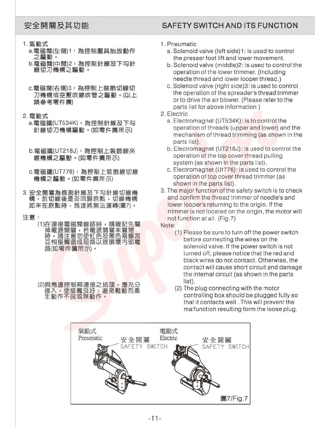
3.
The major function of the safety switch is to check
and confirm the thread trimmer of
needle's and
lower looper's returning to the origin. If the
trimmer is not
located on the origin, the motor will
not function at all. (Fig.?)
Note:
(1)
Please be sure to turn
off
the power switch
before connecting the wires on the
solenoid valve. If the power switch is not
turned
off, please notice that the red and
black wires
do
not contact. Otherwise, the
contact
will cause short circuit and damage
the internal circuit (as shown
in
the parts
list).
(2)
The plug connecting with the motor
controlling box should be plugged fully so
that it contacts well . This will prevent the
malfunction resulting form the loose plug.
~111~
Pneumatic
3i:
~
00
IHl
Electric
!fi~OOIUJ
SA
FE
TY
SWITCH
SAFETY
SWITCH
!117/Fig.?
-
11
-
From the library of: Superior Sewing Machine & Supply LLC
 Loading...