:
I
I
I
I
-------------------------------------------------~-----------------------------------------1
I
~~jl2~~7]~
INSTALL THE MOTOR l
-------------------------------------------1
1.
9f;~IJ,~iq]ij~JffiB~
A
~diRU
B
11lic7B
r.&iimffl
,
Pfflic~m~
6mm
c
Ill
19)
8
A
2.~-SIR~~~~~,~~~®,§
miRfi®,~~®,m~~®&~•@,
~~m®~"-
o c • 20)
3-~~-®~awd~9G5da•,~•
~IR~m§m.t.75
,
IDi~~'J'~i~JR,!f.§
•®w~m®~•roGIDi~~~~®~
~·@.t.~iliffiWd~&'J'~iq]fH~·@
dSJ~~-,
~!I**CV~'J'!Wi~lti,~-@
@l~~~RJ:
o C
I;J
20
, 21)
-23-
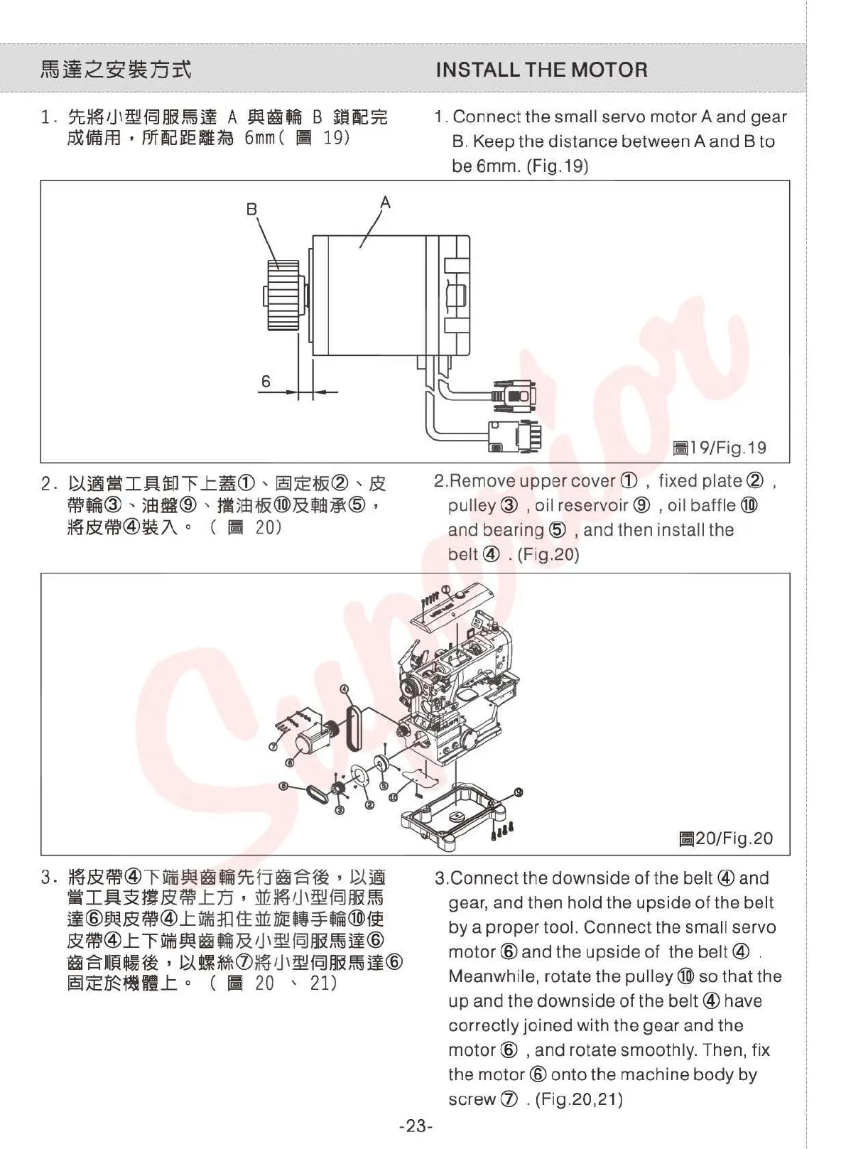
1.
Connect the small servo motor A and gear
B.
Keep the distance between A and B to
be 6mm. (Fig.19)
!1]19/Fig.19
2.Remove upper cover
CD
, fixed
plate®
,
pulley@
, oil reservoir@ , oil
baffle®
and
bearing@
, and then install the
belt@
. (Fig.20)
[;120/Fig.20
3.Connect the downside
of
the
belt@
and
gear, and then
hold the upside
of
the belt
by a proper tool. Connect the small servo
motor@
and the upside of the
belt@
.
Meanwhile, rotate the
pulley®
so that the
up and the downside of the
belt@
have
correctly joined with the gear and the
motor@
, and rotate smoothly. Then, fix
the
motor@
onto the machine body by
screw
CV
. (Fig.20,21)
I
!
I
!
I
I
I
I
i
!
i
!
From the library of: Superior Sewing Machine & Supply LLC
 Loading...