i-
J\
~
~fi·;f:H~f
fJLfti'J{J
lf.l1~(0023)
I
The
timing of looper
in
reference
to
needle (Fig.23)
0023
Fig.23
m#~
•
~~~
.
~#m~aJE.•~m~cm~•nm
fff5J~imJ~(.t.IIJ0023)o
The looper shall be moved backward to the lowest position
while the needle is at the bottom dead centre; loo
se
n the screw on
the gear and make timing adjustment
of
the looper in relation to the
needle (refer to Fig 23.)
i-JL.
~fi-I¥J~~If(0024)
I Thread-guiding amount
of
the looper (Fig.24)
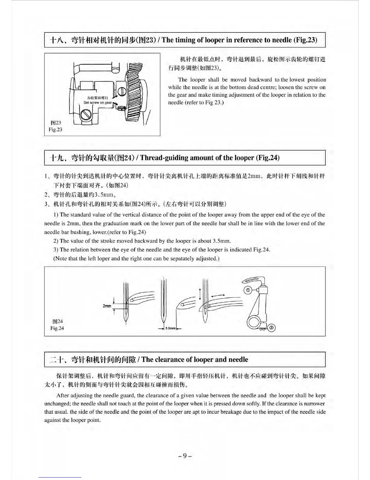
1.
~tta~uqc~IJit-tJL-tta~~
.C
.'1!l::i!:A>t.
~tl·~-qc~m~-:fLJ:!Jffilfi::~ie~~i'f£it:ll2mm,
JltA>t
-tl·f-T-r~
IJ
~fo~-.t:f
-rM-~r~lffiooM1f
0 (
1.m0024
)
2,
~ti"~JE
:itHII:r.J3.
5mmo
3,
tJ
Ltt:fL
fo
~~
·
1L~;f§M5c
~
.t.to
(002
4)
W!"Jft
o
(ti::tl~tl-
l'lJ
l;HHJIJimJ~
)
1)
The
standard value
of
the vertical
di
stance
of
the point
of
the looper away from the upper
end
of
the eye
of
the
n
ee
dle is 2mm, then the graduation mark on the lower part
of
the needle bar shall be
in
line with the lower end
of
the
n
ee
dle bar bushing, lower.(ref
er
to Fig.24)
2)
The
value
of
the stroke moved backward by the l
ooper
is about 3
.5mm
.
3)
The
relation between the eye
of
the needle and the eye
of
the looper is indicated Fig.24.
(Note that the left Ioper and the ri
ght
one can be sepatately adjusted.)
0024
Fig.24
2mm
§t~-•~mJE,
mu~~t~-~@00~
-
~~•,
~m¥m&ffim#
,
m#~~@·~~uuqc
o
~•~•
*~T,mt~-~~w~~U#~a~~~~••ffiam
o
After adjusting the needle guard, the clearance
of
a given value between the needle and the looper shall be kept
unchanged; the needle shall not touch at the point
of
the looper when
it
is pressed down softly.
If
the clearance is narrower
that usual. the side
of
the needle and the point
of
the looper are apt to
in
cur breakage due
to
the impact
of
th
e needle side
against the looper point.
-9-
 Loading...