t1Li~1l»A~
I Specification
~~~~
~
)~
~~*It
#fffi~
:«
tt
iitl
ie
1t'HU
~~~~J't
~
tj
-
i*
#WJ
~fN;ffi}l!ll
i
tt
~
ilflilt~
1H
tJ~
tf-~
~UiJ:\!ii
Ri
1Jj4Jj;Jtl1jl4500~
l.4
~4
m
m
3
0mm
1/8"
5/
32
" 3/
16
" 7/
32"
1/
4"
5/1
6"
3/
8"
1/2"
fi
·
H~t
~
~
!l!:ftiJWi'i J:\
~
118
"
~
1
/
2"jl!iffl
i
1fi
741~\
'
rei!
~
):\
*
ffl
J:::1Hi
8~
1
0m
m
ntJl
~
2%8
ilir
"S
tit
ch
type
S
pe
ed
Stitch
leng
th
Stroke
of
n
eed
le
bar
Gauges
of d
ou
bl
e
-row
Thr
ead
tak
e
-up
type
Looper
Needle
gu
ar
d
Light
clearance
of
knee
li
fter
Oil
s
uppl
y
Lubricating
oil
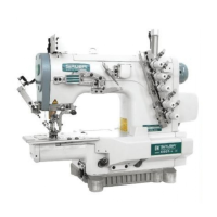
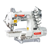
Two
-n
eed
le
do
ubl
e-row
ch
ain
s
ti
tch
Max.4,500
s
.p
.m.
1.4
~
4mm
30m
m
118"
5/
32"
3/1
6"
7/
32
"
1/4"
5/16"
3/
8"
112"
Nee
dl
e bar
thr
ead
t
ake
up
type
Separately
ad
ju
ta
bl
e
type
,
for
th
e
range
of
1/8
"
to
1/2"
Oscillating
t
ype
a
nd
ri
g
id
type
8~
l0mm
lmp
e
ll
er
-t
ype
pump
#2
wh
il
e
oil
I!Y
..
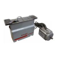
:lJLI~l'l{]~~(001)
/Installation
of
the machine (Fig.l)
001
Fig. l
jlf
!f
flll
Nearbodyside
t~
\ii
l(l
Hinge si
de
I .
M:at~~-=
·M·~-
OO
~M:at
•
®
·~~-m~~~
ifi,
fflila:at~tr
Q)
•
:Jt
re!J/E,
fi}~J:M:at
o
(~I)
2.am~~-~~A••~~.
~~•~m~~•~•m•
~.
w
•·~~~~fljfi~
-
~-
l:o
l.
To
in
stall the o
il
reservoir.
Put the o
il
r
ese
rvoir rubber cushion
OO
and o
il
reservoir fe
lt
cushion
Q)
oo
four
corners
of
the opening
of
the tabl
e,
fix them with the
wood screws
<I>
,then install the oil reservoir (Fig I)
2. Put the machine conn
ec
ting hooks into the hol
es
to engage respe-
ctively two hinges seated in
the
table,then place the machine
on
the four cushions.
1i
..
JJnilfJ(002
..
003) I Oiling (Fig.2
..
Fig.3)
002
Fig.2
003
Fig.3
1.
lf:iJilb:at~1Jli
~~
JJmM
(2"%
8
M)
~
lllGHic
-%ffl
H
!L(I¥J2
)o
2.
-
~o
*
nn
ffff
fl
.Ff
Low
ic
-
~
,
m w
»oilE
0
3,
)
JliM
J§JF~tJm~,
wHJtlE'ffi"Ht
,
m~H~IJiltmlnY!¥1JM~
J:
(003)
.
~
~·~ilE
~l:
~MM
~~~
~MM
~
·~~*
·~~~
4.~---~.
RWm~M:at~mM•tr.
~ilERftmllio
s.Rmam•~*M*Rm~~mm~.
•msffi•~•*
tJ
I•
3
500
-4
000tl
·a'oJ:ia!Jt~f!<~
I 0
7H
ijl
0
l.
Oiling sha
ll
be made
in
oi
l
re
servoir and the oil surface also be made
to level the mark
"I-Ugh
'
1
befo
re
the machine
is
started running (Fig.2)
2.
Oiling shall be kept on until the o
il
surface has been brought above
the
mark"Low" (Fig.3)
3.
The normal condition
of
lubrica
ti
on is that
th
e oil sha
ll
spr
ay
onto the
oil sight. The amo
un
t
of
oil spray
in
g onto
th
e o
il
sig
ht
is not
at
all
proportional to the total amount of o
il
in
the o
il
reservoir. There is
nothing
to
worry about.
4.
Only when
th
e
dr
ain cover screw is loosened and taken
off
ca
n o
ld
oi
l be dra
in
ed out a
nd
new oil is supplied again.
5. When a new
mod
el or those standing
idl
e for long time is to be ope-
rated,presser foot shall be lifted and run idle
for about ten minutes.
-2-
 Loading...