EasyManua.ls Logo

SiTime SiT6731EB - User Manual

Default Icon
9 pages
Print Icon
To Next Page IconTo Next Page
Loading...
SiT6731EB Manual Rev. 3.0
Page 1 of 9
www.sitime.com
SiT6731EB Evaluation Board
User Manual
Contents
1 Introduction ............................................................................................................................................. 1
2 I/O Descriptions ....................................................................................................................................... 2
3 EVB Usage Descriptions ........................................................................................................................... 2
3.1 EVB Configurations .......................................................................................................................... 2
3.2 Waveform Capturing Using Active Probe ........................................................................................ 4
3.3 Measuring Jitter and Phase Noise ................................................................................................... 5
3.4 Current Measurement ..................................................................................................................... 5
Appendix A .................................................................................................................................................... 6
1 Introduction
The SiT6731EB evaluation board (EVB) is designed for use with SiTime’s Emerald OCXOs in the 10-pin
9x7 mm package. It enables the evaluation of key functionalities of these OCXOs.
EVB Features
- SMA output for direct or buffered connection to measurement equipment
- Probing points for accurate waveform measurement
- Provision for I
2
C control interface (connector)
SiTime typically ships the EVB with the OCXO mounted. The OCXO device should only be evaluated in its
original soldered down state for best signal integrity and frequency stability. For best results the device
should not be de-soldered and then re-soldered either manually or via reflow process.
Question and Answer IconNeed help?

Do you have a question about the SiTime SiT6731EB and is the answer not in the manual?

Summary

Introduction

I;O Descriptions

EVB Usage

EVB Configurations

Details how the EVB supports OCXO/DCOCXO devices and output access methods.

Waveform Capturing Using Active Probe

Explains critical logic and high-frequency measurement techniques using high-quality active probes for best results.

Measuring Jitter and Phase Noise

Recommends buffered output for jitter/phase noise measurements and connection to instruments like TIA.

Current Measurement

Guides on using ammeter/multi-meter for current consumption, including VDD adjustment.

Appendix A

Overview

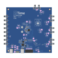
The SiT6731EB Evaluation Board (EVB) is a specialized tool designed for the assessment of SiTime's Emerald OCXOs, specifically those housed in a 10-pin, 9x7 mm package. Its primary function is to facilitate the evaluation of the key functionalities of these high-performance OCXOs.

Function Description:

The SiT6731EB EVB serves as a platform for comprehensive testing and characterization of SiTime's Emerald OCXOs. It allows users to:

  • Access Oscillator Output: The board provides multiple ways to access the oscillator output, including direct output through an SMA connector, buffered output through an SMA connector, oscilloscope probe at designated probing points, and direct output through an LVCMOS-to-sinewave filter and SMA connector. This versatility ensures compatibility with various measurement setups and signal analysis requirements.
  • Power Supply and Sensing: It includes a 4-pin connector (P1) for DC power supply and power sensing, with VDD connected to Pin 1, GND to Pin 2, VDD sense to Pin 4, and GND sense to Pin 3. This allows for precise control and monitoring of the power supplied to the OCXO.
  • Frequency Control via I²C: A 3-pin header (P3) provides access to the I²C (SDA, SCL) bus, enabling configuration and control of DCOCXOs. This feature is crucial for dynamic adjustment and testing of frequency parameters.
  • Pin 1 Access: A 2-pin connector (P2) offers access to Pin 1 of the OCXO in OE (Output Enable) mode. In OE mode, Pin 1 can be left floating due to an internal pull-up resistor, simplifying certain test scenarios.

Important Technical Specifications:

While the manual doesn't list explicit technical specifications for the EVB itself, it details component configurations and recommendations crucial for accurate measurements:

  • Output Configurations: The board supports various output configurations (Direct, Direct + LVCMOS-to-sinewave filter, Buffered output: LVCMOS, Clipped Sine, Probe: LVCMOS, Clipped Sine) by adjusting specific components like capacitors (C3, C5, C8, C9) and resistors (R11, R13, R14, R20). For instance, a 0.1 uF/0 Ohm C5 is used for direct output, while a 0.1 uF C5 and 20 KΩ R13/R14 are used for buffered clipped sine output.
  • Load Matching: The values of the load capacitor C3 and load resistor R11 can be adjusted to match the load conditions of the target application. This allows for measuring waveform characteristics under conditions as close as possible to the final product's environment.
  • LVCMOS-to-Sinewave Filter: The component values for the LVCMOS-to-sinewave filter are dependent on the carrier frequency of the device. Users are advised to contact SiTime for recommended nominals for these filter components.
  • Buffered Output: For jitter and phase noise measurements, a buffered output configuration is recommended. The board utilizes an LMK1C1104 low-additive jitter buffer (U2) to minimize the impact on measurements, as SiTime OCXOs are not designed to directly drive a 50 Ω load.
  • Bill of Materials (BOM): The manual provides a detailed BOM (Table A1) listing components such as capacitors (10uF, 0.1uF, 1uF), resistors (800 Ω, 0 Ω, 49.9 Ω, 8.2 KΩ), an LED (Green), an SMA connector, a Ferrite Bead (600 Ω @ 100 MHz), and various headers and connectors. This provides a clear overview of the board's construction.

Usage Features:

  • Pre-configured Shipment: The SiT6731EB is typically shipped configured for buffered output, allowing direct connection to instrument inputs using a 50 Ω coax cable. This facilitates immediate use upon receipt.
  • Active Probe Waveform Capturing: For accurate waveform measurements of the high-speed logic output, SiTime recommends using specific equipment: a 4 GHz or higher active probe with capacitance <1 pF (e.g., Keysight 1134B) and an oscilloscope with 4 GHz bandwidth or higher (e.g., Keysight DSA90604A). Passive voltage probes are discouraged due to their high capacitive load and long ground leads, which can distort the clock signal.
  • Optimized Probing Points: Test points for active probes are strategically placed close to the oscillator output to ensure better signal integrity. For waveform measurement, removing capacitor C5 is recommended. If a soldering probe head is used, it's advised to use the R11 resistor pads or solder over them if necessary.
  • Jitter and Phase Noise Measurement: The SMA connector can be directly connected to jitter measurement instruments like Time Interval Analyzers (TIA) or high-bandwidth real-time oscilloscopes. For phase noise measurements using signal source analyzers or spectrum analyzers, AC-coupling configuration is recommended to accommodate instruments that may not accept DC voltage inputs.
  • Current Measurement: To measure current consumption, users should employ an ammeter/multi-meter in the power supply circuit. It is recommended to remove diode D1 to avoid measuring its additional current. Users should also measure the voltage on the DUT VDD and adjust for any drop on the DMM to ensure a known VDD voltage on the device, with VDD adjustment completed before each current measurement.

Maintenance Features:

  • Original Soldered State: SiTime emphasizes that the OCXO device should only be evaluated in its original soldered-down state to ensure optimal signal integrity and frequency stability. De-soldering and re-soldering, whether manually or via reflow process, is strongly discouraged as it can compromise performance.
  • Internal Use Connectors: Connectors P4 and P5 are reserved for SiTime internal use only, indicating that users should not attempt to modify or utilize these points.
  • Component Configuration Flexibility: The ability to adjust C3 and R11 for load matching, and the guidance on contacting SiTime for LVCMOS-to-sinewave filter component values, allows for a degree of customization and maintenance to adapt the EVB to specific test requirements and ensure accurate results over time.

SiTime SiT6731EB Specifications

General IconGeneral
BrandSiTime
ModelSiT6731EB
CategoryMotherboard
LanguageEnglish

Related product manuals