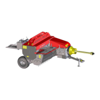
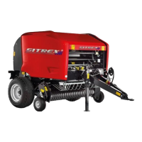
The device described in this manual is a Sitrex Square Baler, available in three models: M 60 Mini/S, M 60 Mini, and M 60 Super. It is an agricultural machine designed for baling hay, straw, and other similar materials.
Function Description
The primary function of the Sitrex Square Baler is to collect loose agricultural material (like hay or straw) from the ground, compress it into rectangular bales, and tie these bales with twine for easier handling, storage, and transport. The baler is typically towed by a tractor and powered by its PTO (Power Take-Off) shaft.
Key operational steps include:
- Picking up material: The pickup mechanism gathers material from the swath on the ground.
- Conveying and feeding: The collected material is conveyed into the bale chamber by feeder forks.
- Baling: Inside the bale chamber, the material is compressed by a plunger into dense, rectangular bales.
- Tying: Once a bale reaches the desired length and density, the knotter system ties it with twine.
- Ejection: The finished bale is then ejected from the machine, often onto a chute or trailer.
The manual emphasizes the importance of proper operation and maintenance to ensure optimal performance and safety.
Important Technical Specifications
The manual provides a table of specifications for the three models: M60 Mini/S, M60 Mini, and M60 Super.
General Specifications:
- Bale chamber: 34x44 (13.4x17.3) cm (in) for all models.
- Straw bale weight: 13-20 (28-44) kg (lb) for all models.
- Hay bale weight: 18-28 (39-62) kg (lb) for all models.
- Bale length: 40-130 (16-51) cm (in) for all models.
- Bale production capacity/minute: 3-9 for all models.
- Plunger strokes/minute: 80-90 for all models.
- P.T.O. power requirement: CV(HP) 20-25 (20-25) for all models.
- Maximum pickup width: 90 ÷ 95 (35-37) cm (in) for M60 Mini/S and M60 Mini; 105 (41) cm (in) for M60 Super.
- Weight: 850 (1874) kg (lb) for M60 Mini/S; 900 (2000) kg (lb) for M60 Mini; 1000 (2205) kg (lb) for M60 Super.
- Overall width: 169 (66,5) cm (in) for M60 Mini/S; 180 (71) cm (in) for M60 Mini; 210 (83) cm (in) for M60 Super.
- Overall width with side wheel mounted behind the pickup: 149 (58,7) cm (in) for M60 Mini/S; 160 (63) cm (in) for M60 Mini; 190 (75) cm (in) for M60 Super.
- Length: 395 (155) cm (in) for all models.
- Height: 135 (53) cm (in) for all models.
- Tires: 7.00/12 or 195/75-14 165/80-13 for M60 Mini/S and M60 Mini; 7.00/12 or 195/75-14 165/80-13 for M60 Super.
Standard Equipment:
- Twine knotter
- Pickup lift crank
- Bale counter
- PTO shaft
- Third wheel bracket
Optional Equipment:
- Third wheel
- Third wheel with bracket
- Pickup wheel
- Hydraulic pickup lift
- Hydraulic drawbar adjustment
- Wide-angle PTO shaft
- Long chute and trailer hitch
- Lights kit
- Pickup support roller
Tire Pressure:
- 7.00/12 (6PR): 2.0 Bar (2.5 MAX)
- 195/75-14 (6PR): 2.0 Bar (2.5 MAX)
- 165/80-13 (8PR): 3.2 Bar (4.5 MAX)
- 10.0/80-12 (8PR): 2.2 Bar (2.5 MAX)
Usage Features
The manual details various aspects of using the baler, emphasizing safety and proper setup.
Safety:
- WARNING! The manufacturer of the PTO shaft or universal joint is responsible for these components. The baler requires the specified EEC declaration of conformity together with the machine.
- Familiarize yourself with controls and correct use.
- Keep animals and other people away from the machine.
- Wear suitable clothing and heavy-duty shoes.
- Ensure protective systems, guards, and safety devices are in accordance with regulations.
- Stop the machine before crossing roads, country roads, or paths.
- If the machine vibrates excessively, turn off the engine, check for damage, and have all necessary repairs done by qualified personnel.
- Stop the engine, apply the parking brake, and remove the key before getting off the tractor.
- Wait until all moving parts have stopped before approaching the machine.
- Keep hands and feet away from moving parts.
- Always keep in mind the usage and accident prevention rules.
- The operator should familiarize himself with the machine, its parts, and their functions.
- Always check that the machine is perfectly clean to avoid dangerous accidents.
- Do not tamper with the safety systems or controls.
- Ensure that lights, warning signs, and protective devices are installed and working.
- The operating speed must be compatible with environmental conditions.
- Avoid making sudden or sharp turns when going uphill or downhill.
- The machine can be started only when protective devices are installed.
- Make sure there are no persons near the machine during operations involving tipping and moving hydraulic parts.
Putting into Operation:
- Checks before putting into operation: Lubrication, adjustments, attachment to the tractor, transporting the machine, setting up for work, loading the twine, baling, adjustments, maneuvers at the end of the row, setting up for transport, and parking the machine.
- Hitching to the tractor: Position the baler on adequate firm, flat ground, and place the parking stand so that the bale chamber is parallel to the ground. The towing eye should be 30-60 cm from the PTO and the transverse position of the eye must be such that it is 0 to 5 cm to the right with regard to the axis of the tractor PTO. Secure the hitch pin with a suitable locking pin.
- Transporting the machine: Ensure overall dimensions are in compliance with local laws. Check the condition of the tires, remove the PTO shaft, put the drawbar in the transport position, close the bale discharge chute, raise the pickup to the transport position, and ensure no people or objects may fall off the machine.
- Loading the twine: Insert the spools of twine into the twine box. Ensure twine unwinds counterclockwise when you pull the central end. Thread the twine as shown in Fig. 5.8. Adjust the twine tension (see section 7.4.6). Tie the ends of the twine to the lower crossbar of the bale chamber. Fully raise the lever 1 which can be seen in Fig. 5.10 to engage the knotter. Rotate the flywheel anticlockwise to set the needle/knotter system in motion until the twine is held in the twine holder disc. Continue rotation until the needle holder arm is in the rest position with the needles retracted. Remove the two pieces of twine that are still tied to the crossbar.
- Baling: Put the machine into operation, proceed as follows: Lower the bale discharge chute and reduce the tension of the bale chamber springs by adjusting the cranks 4 in Fig. 5.10. Adjust the height of the pickup from the ground.
Maintenance Features
Regular maintenance is crucial for the longevity and efficient operation of the baler. The manual provides a detailed maintenance table and instructions for various adjustments.
General Maintenance:
- Lubrication: Grease points (1,2,3,4,5,6,11,13) every 8 workhours.
- Grease: Grease points (7,12) every 40 workhours.
- Grease: Grease point (14) every 250 workhours.
- Grease: Grease point (15) every 500 workhours/season.
- Lubricate chains: Every 8 workhours.
- Clean and blow out knotter compartment: Every 8 workhours.
- Clean bale chamber: Every 8 workhours.
- General cleaning: Every 8 workhours.
- Change oil: Every 500 workhours/season.
- Check carriage-chamber knife adjustment: Every 500 workhours/season.
- Check tension belt: Every 500 workhours/season.
- Check pickup cam: Every 500 workhours/season.
- Check brake: Every 500 workhours/season.
- Check tire pressure: Every 8 workhours.
- Check tightness of nuts, bolts, screws: Every 8 workhours.
- Check carriage-chamber knife: Every 500 workhours/season.
- Check twine: Every 8 workhours.
- Check protection systems: Every 8 workhours.
- Check that needle rollers rotate freely: Every 8 workhours.
- Check hydraulic hoses for fluid leaks: Every 8 workhours.
- Check safety decals: Every 8 workhours.
- Check wear of twine guides: Every 8 workhours.
- Check wear: Every 8 workhours.
- Check electrical system: Every 8 workhours.
Maintenance Materials:
- Hydraulic fluid: ENI MULTISCH 15W-40 (Qty. MAX 2 LT, Position Point A)
- Chain lubrication: ISO VG 100
- Gearbox: SAE 90-120 -140EP
- Feed box: Grease (Position Point 15)
- Grease: ENI NLGI 2 (Position Points 1,2,3,4,5,7,11,12,13,14)
- Sisal twine: 180-200 m/kg
- Nylon twine: 350 m/kg
Safety Device Replacement:
- All parts of the baler are protected by devices designed to interrupt transmission when irregular operation occurs.
- The machine has the following safety systems: Flywheel clutch, Flywheel shear bolt, Pickup control safety device, Knotter control shear bolt, 1st fork shear bolt, 2nd fork shear bolt.
- To avoid altering the operation of these safety devices, restore them with components having equivalent mechanical specifications.
Adjustments:
- Tongue adjustment: The baler tongue must be adjusted according to the tractor, so that the chamber is level with the ground.
- Drive adjustment (TIMING): Timing of the forks with the carriage (A), and the knotter/needles with the carriage (B).
- Forks/carriage timing (A): Make the connection with the chain 10 (Fig. 7.3) between the gear 1 (Fig. 7.3) and the gear 2 (Fig. 7.3) on the fork control. Move the carriage forward up to the reference position A (tips of the carriage in the plane of the fork passage slot). The distance between the fork and the bale chamber should be about 65 to 95 mm. The fork is mounted with the inclined side towards the bale chamber. The fork is mounted with the perpendicular side towards the bale chamber. The gear 1 is secured to its axle with the Allen screws.
- Knotter/needles timing with the carriage (B): Make the gear 7 idle by removing the chain 1 (Fig. 7.7). Put the needles in the rest position by bringing the needle holder arm 5 (Fig. 7.7) back to the end of the stroke. Engage the knotter by bringing the sector lever 4 (Fig. 7.7) to its maximum height by rotating the bale star wheel spacer 6 (Fig. 7.7). Manually rotate the bale gear 3 (Fig. 7.7) counterclockwise until it locks in the dragging position of the knotter shaft. Continue to rotate the bale gear 3 (Fig. 7.7) counterclockwise, moving it repeatedly with a series of "clicks," until the needle holder arm is lowered so that the needle tips are level with the lower edge of bale chamber (Fig. 7.7).
- Bale chamber adjustment: The belt that transmits power to the pickup must be correctly tensioned; the tension can be increased or decreased by means of the tensioner (ref. 13 Fig. 7.7). The correct tension is checked as follows: applying a force F of 60 N (Fig. 7.7) - applied at the middle of the free side directed perpendicular to the belt itself, the belt must have a maximum deflection of 8 mm. The chains must be tensioned for correct use.
- Plunger guides adjustment: The plunger is mounted on sealed bearings and is guided by steel blades. The bale chamber has slides on adjustable steel guides. The lateral movement must be made such as to leave a space of 0.5 mm in which the plunger can move. Despite the minimal play, the plunger must not be stopped in its stroke. This adjustment should be done rarely, unless it is noted that the plunger has too much play. To obtain the correct clearance of the plunger, it is necessary to adjust the left side guides of the plunger.
- Bale chamber knives adjustment: The knives (fixed on the chamber, ref. A, and ref. B on the carriage, Fig. 7.10) are designed to separate successive layers of material sent into the bale chamber by the feeder forks. It is very important to adjust the knives to obtain quality bales and to avoid frequent breakage of the shear bolt on the flywheel. The distance between the knife fastened to the bale chamber and the movable knife fastened to the plunger should be 0.8-1.5 mm. This play must be as little as possible but such as to allow free movement of the plunger in the bale chamber.
- Knotter adjustment: There are several possible knotter adjustments, and they are generally necessary only when there is wear on the components.
- Knotter brake adjustment: This brake (ref. 7 Fig. 7.11) is designed to make the motion of the knotter uniform during the tying cycle and to hold it still when it is not working. The adjustment is done by turning the adjustment screw to increase or decrease the compression on the spring 5 (Fig. 7.11). The reference measure H = 25 mm.
- Holder disc pressure adjustment: Make this adjustment with 1/3-1/2 of a turn for each attempt. The pressure of the holder discs must hold the twine pulled taut by the proceeding of the bale, but at the same time it must allow the knotter billhooks to extract the amount of twine necessary to form the knots. The pressure is adjusted by adjusting the flat spring 1. To do this, loosen the lock nut 3 and turn the screw 2 (Fig. 7.12). To find the correct holder disc pressure, proceed as follows: the twine must be inserted and pressed in the holder disc. Adjust the spring 1 in Fig. 7.12 as described previously, so that the twine runs only when subjected to a force E of 40 to 60 kg. If necessary, adjust the flat spring 1 (Fig. 7.12) until the distance A is approximately 2–3 mm.
- Needles adjustment: The needles are adjusted using screws 1 and 2 as shown in Fig. 7.14. To reduce the distance between the needle tips and the holder disc when they bring the thread to the knotter, loosen screw 2 by a fraction of a turn and tighten screw 1 by the same amount. To increase the aforementioned distance, make the adjustment in the opposite manner. To move the needles sideways, bend them as much as necessary. The distance between the side of the needle and the knotter frame must be 0.5 to 1 mm.
- Crescent aligner/twine guide cam adjustment: The play between the twine guide cams 3 (Fig. 7.15) and their pins must be the minimum needed to allow them to move freely. In the rest position, the tips of the twine guide cams must be in line with the edges of the passage holes for the twine carried by the needles, with a maximum tolerance of 2 mm towards the inside.
- Twine tension adjustment: Each twine must come out of the clamp (ref. 1, Fig. 7.17) when subjected to a force F1 = 2–3 kg (Fig. 7.17) and must run along its path outside the needle when subjected to a force F2 = 10–14 kg (Fig. 7.17). If necessary, adjust the pressure of the clamp 1 (Fig. 7.17) with the screw 2 (Fig. 7.17).
- Knotter billhook tongue adjustment: With the knotter in the rest position, the billhook tongue (ref. 1, Fig. 7.18) must open if subjected to a force between 5 and 10 kg. If necessary, tighten or loosen the spring (ref. 2, Fig. 7.18).
- Ejector arms and knife holder adjustment: The ejector arms and knife holder (ref. 8 Fig. 7.19) must cut the excess twine and pull the knots out of the knotting billhooks. There is no adjustment for the knives. It is only necessary to keep the knife sharp or to replace it. The adjustment of the ejector arms instead is very important, and must meet the following requirements: In its movement, the ejection tongue (ref. 4, Fig. 7.20) must rub with a slight pressure against the back of the knotting billhook (ref. 2, Fig. 7.20). The tongue is curved to follow the back of the knotting billhook. The curve of the tongue must be centered with the back of the aforesaid billhook. During the ejection movement, the tongue must go beyond the tip of the billhook by no less than 6 mm and no more than 12 mm (ref. L, Fig. 7.20).
- Bale length adjustment: Adjustments are made with the adjustment screw (ref. 3, Fig. 7.21), after loosening the lock nut. For shorter bales, screw in the adjustment screw, moving it upward. For longer bales, unscrew the adjustment screw, moving it downward. The length of the bales can vary from 40 to 130 cm.
- Chamber filling adjustment: The first rule for obtaining perfectly shaped bales is to feed the baler at a constant rate, without overloading. This means having a uniform swath of material to be baled, moving forward steadily and uniformly with the tractor, and adjusting the forks to fill the chamber evenly.
- Bale density (weight) adjustment: The weight of the bales is determined by the quality of the material to be baled and the density and length of the bales. The density can be adjusted by turning the cranks 6 (Fig. 7.24); screwing in the cranks brakes the outgoing material more and increases the density of the bale. To further increase the density, straw trap wedges 3 (Fig. 7.24) are inserted into the appropriate holes in the bale chamber.
- Forks adjustment: In certain conditions there is the need to change the position of the forks. The adjustment for the first fork was described in sect. 7.5.2; for the second fork, the adjustments are described in the following paragraphs.
- Pickup adjustment: This component collects the material to be baled and conveys it to the feeder forks. A certain number of spring-loaded teeth brush against the ground and, after having lifted the material to the maximum height defined by their rotation, they retract with a movement brought about by a special cam. The pickup has two positions: Transport position and Working position.
- PTO shaft overload clutch adjustment: The torque limiter clutch on the flywheel is usually supplied with a standard calibration of 59 daNm and springs (ref. 5, Fig. 7.28). This clutch can be adjusted by means of the bolts 3 (Fig. 7.28), which compress the springs 5. If the clutch plates are in good condition, the correct height H should be 46.9 mm.
- Plunger safety catch adjustment: This component is designed to protect the knotter needles. It consists of a metal pawl 1 (Fig. 7.29) controlled by the needle holder arm by means of the tie rod 2 (Fig. 7.29).
End of Season Storage:
- Thoroughly clean the inside and outside of the machine.
- Loosen the V-belts.
- Inspect and disassemble moving parts, clean them, and check for wear.
- Oil all parts of the PTO shaft.
- Thoroughly lubricate the machine.
- Clean gears and change oil.
- Protect hydraulic cylinder rods with grease.
- Replace worn or damaged parts.
- Touch up paint defects and spray rust inhibitor.
- Store the machine in a dry, protected environment.
- Inflate tires.
- Make a list of spare parts needed for the next season.
Preparation for the New Season:
- Lubricate the entire machine.
- Check oil level and top up.
- Check that screws and bolts are well tightened.
- Check all machine adjustments and readjust if necessary.
- Check the tension of the V-belt.
- Replace worn parts.
- Repair any damaged parts.
- Check that parts move freely.
- Check safety decals.
- Check that protective guards are mounted and in good working condition.
- Reread the use and maintenance manual.