27
PREPARATIONS FOR USE (RT/5200 MANUAL FOLD)
Once the machine has been prepared, before beginning work read the chapter on “General
Instructions for Use in the Field” (see pg.28)
For the RT/5200 manual fold, lateral arms 1-2 (see page 26) should be lowered beforehand.
To do this, rotate pin 4 so that spring pins 3 on it slides over tab “C”, causing pin 4 to exit from the
hole in the inside pipe of the strut assembly (RH and LH side). Now lower lateral arms 1-2 by
pulling on guards “A-B”.
PREPARATIONS FOR USE (RT/5200 HYDRAULIC FOLD)
To lower the side arms 1-2 (see page 26) of the RT/5200 hydraulic fold, move the distributor lever
3 so as to send fluid through hoses 4-5 to cylinders 6-7, which will close completely, pulling rope 8
at the same time as when moving distributor lever 3, thus making it possible to release catch 9 from
pin 10 (RH and LH side), and then moving distributor lever 3 so as to lower side arms 1-2 down to
the ground. (Cylinders 1-2 are single-acting, so the side arms 1-2 lower by their own weight, and
therefore this operation must be carried out in a suitable area.)
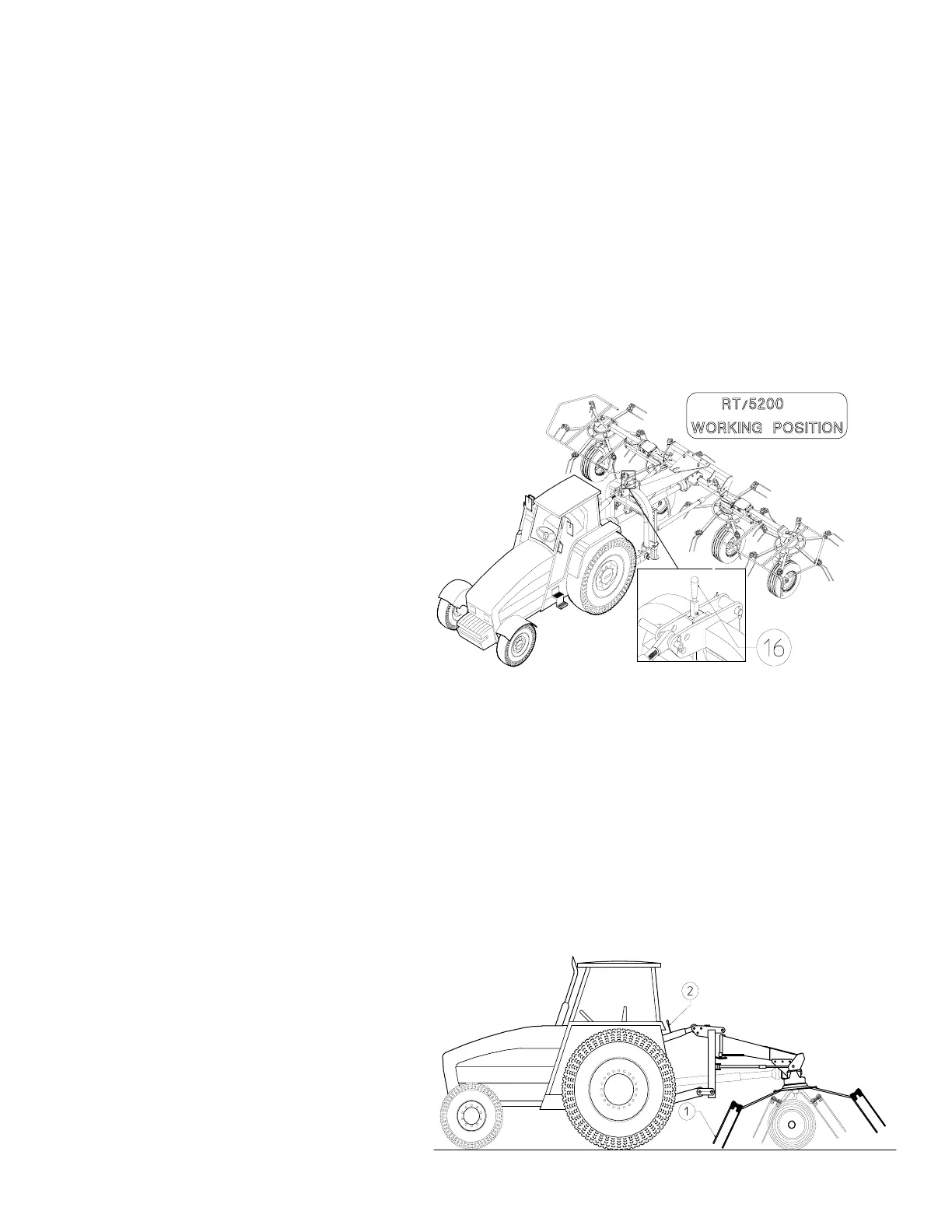
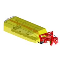
MACHINE READY FOR USE
N.B.: Before starting work, rise the lever 16
so that the 3rd point hitch and the chassis
of the machine are free to sway in respect
of one another.
The figure opposite shows the working
configuration.
Following is a list of settings that
can be made on the machine.
ADJUSTMENT OF SHOCK ABSORBERS
The shock absorbers 11 are gauged by the manufacturer, however their tension can be adjusted to
adapt to the user’s needs. To do this, unscrew the ring nut 13 from the tube 14 and then, with the
help of the lever C, loosen or tighten the sleeve 12 on the tube so as to obtain more or less force
(screwing or unscrewing it respectively). Then fasten the tube 14 and the sleeve 12 in place again
with the ring nut 13.
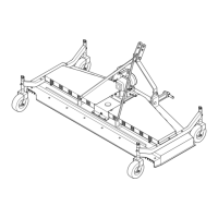
ADJUSTMENT OF WHEEL POSITION
In the normal working position, the wheel supports D must be secured in place by means of the pin
15 in middle hole E. When working along embankments, ditches and so on, and in order to avoid
coming too close or scattering the forage beyond the edge of the field, it is possible to move the
wheel supports D to one side or to the other by inserting the pin 15 into the side holes F or G.
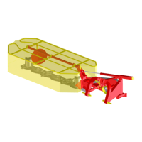
ADJUSTMENT FOR CORRECT
WORKING POSITION
These machines are very easily adjusted.
For best operation, the tines 1 on the front
side of the machine should brush the
ground. To obtain this, turn the adjustment
tie rod (or hydraulic cylinder) 2.