25
Top-Plate Sharpening Angles
(Fig. 22)
CORRECT 30°- This optimal angle can be
obtained only when the specied les and
proper setting are used. File holders are
marked with guide marks to align the le
properly to produce the correct top plate angle.
LESS THAN 30°- The tooth is too dull for
cutting.
MORE THAN 30°- The edge of the cutting
tooth is feathered and dulls quickly.
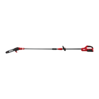
Side-Plate Angle (Fig. 23)
CORRECT 60°- The optimal angle can be
produced automatically if the correct diameter
le is used in the le holder.
HOOK- “Grabs” and dulls quickly. Increases
potential of KICKBACK. Results from using a
le with a diameter that is too small, or a le
held too low.
BACKWARD SLOPE- Requires too much feed
pressure, causes excessive wear to bar and
chain. Results from using a le with a diameter
too large, or a le held too high.
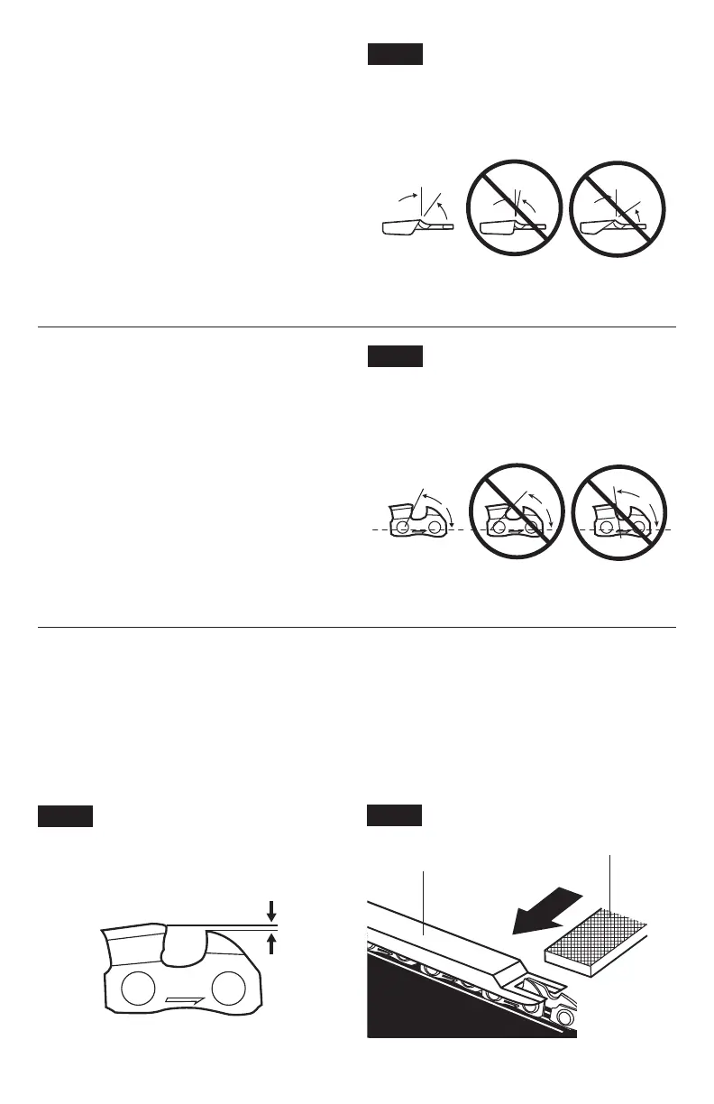
Depth-Gauge Clearance
1. The depth gauge should be maintained at a clearance of 0.025 in. (0.6 mm), as shown
in Fig. 24. Use a depth-gauge tool (available separately) to check the depth-gauge
clearances.
2. Check the depth-gauge clearance every time the chain is led. Use a at le and a depth-
gauge jointer (both available separately) to lower all gauges uniformly (Fig. 25). Depth-
gauge jointers are available in 0.020 in. to 0.035 in. (0.5 mm to 0.9 mm). Use a 0.025 in.
(0.6 mm) depth-gauge jointer.
Fig. 24
Depth Gauge Clearance
0.025" (0.6mm)
Fig. 25
Depth Gauge
Jointer
Flat File
30°
Fig. 22
Top Plate Sharpening Angles
Less
than 30°
Correct Incorrect Incorrect
More
than 30°
60°
Fig. 23
Side Plate Angle
Hook
Correct Incorrect Incorrect
Backward
Slope
 Loading...