8
SYMBOLS (CONTINUED)
IMPORTANT: Some of the following symbols may be used on your tool. Please study them
and learn their meaning. Proper interpretation of these symbols will allow you to operate the
tool better and more safely.
Symbol Name Designation / Explanation
V Volts Voltage (potential)
A Amperes Current
Hz Hertz Frequency (cycles per second)
W Watt Power
kg Kilograms Weight
min Minutes Time
s Seconds Time
Wh Watt-hours Battery capacity
Ah Ampere-Hours Battery capacity
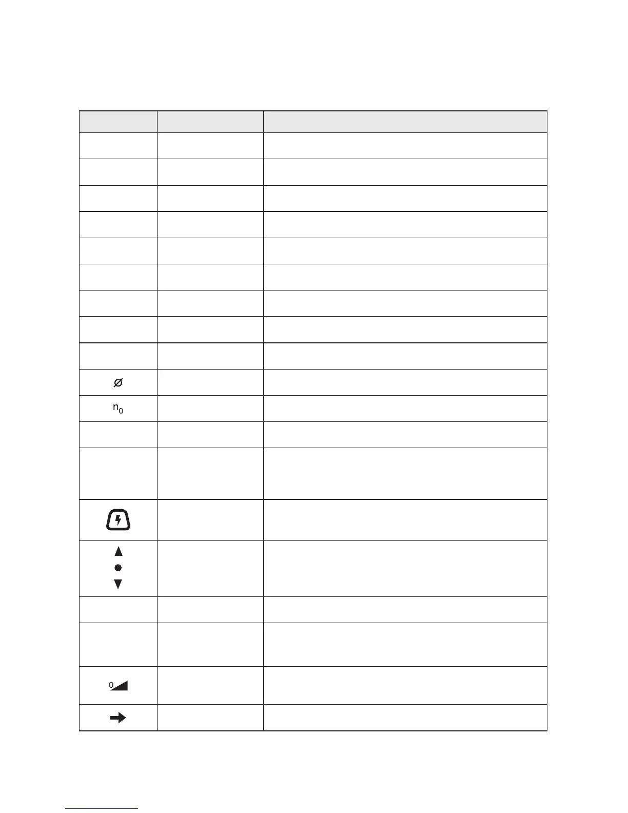
Diameter Size of drill bits, grinding wheels, etc.
No load speed Rotational speed, at no load
n Rated speed Maximum attainable speed
.../min
Revolutions or
reciprocation per
minute
Revolutions, strokes, surface speed, orbits etc. per
minute
Circuit Sensor
button
Depress this button to activate the Circuit Sensor function
Forward/Reverse
Arrow Indicators
Shows the rotation direction
0 Off position Zero speed, zero torque...
1, 2, 3, ...
I, II, III,
Selector settings
Speed, torque or position settings. Higher number means
greater speed
Innitely variable
selector with off
Speed is increasing from 0 setting
Arrow Action in the direction of arrow