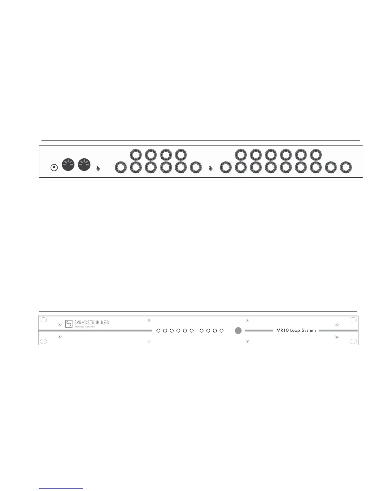
REAR PANEL
9VAC: 2.1mm DC barrel.
MIDI IN: Standard 5pin DIN connector.
The MIDI IN connector must be connected to the MIDI OUT connector of a transmi ng MIDI device via a standard cable, in order for the loop system
respond to MIDI commands origina ng from these devices.
MIDI THRU: Standard 5pin DIN connector.
The MIDI THRU connector will forward the incoming MIDI data to any MIDI device.
GND/LIFT: Mini toggle switch. Set for minimum hum. When in LIFT posi on the audio ground is li ed from the chassis.
LOOP 10 OUT: 1/4” mono jack, which provide an output of the audio signal from Loop 1 - Loop 10, or Loop 6 - Loop 10, depending on how the LINK/GROUP mini
switch is set.
LOOP 7 IN: 1/4” mono jack, that provide input to group 2. Only ac ve when the mini toggle switch is set to GROUP.
This input u lizes our highly recognized high impedance input buff er.
LINK/GROUP: Mini toggle switch. When set to LINK the signal is routed through all 10 loops. Loop 6 OUT and Loop 7 IN is disabled.
When set to GROUP the MR10 is divided into two groups of loops.
Group 1 is loop 1 - loop 6, and group 2 is loop 7 - loop 10. Loop 6 OUT and Loop 7 IN is enabled.
LOOP 6 OUT: 1/4” mono jack, which provide an output of the audio signal from group 1. The output is only ac ve when the mini toggle switch is set to GROUP.
When the mini toggle switch is set to LINK, the output is disabled.
LOOP 1 IN: 1/4” mono jack used to provide input to the MR10 Loop System. This input u lizes our highly recognized high impedance input buff er.
TUNER OUT: 1/4” mono jack. Provides a transformer isolated tuner output.
LOOP RETURN: 1/4” mono jacks that accept the output of any external device. The inser on of a plug will break the internal normalling to the SEND jack.
Each RETURN is fed to a unity gain line driver, which is only ac ve when the loop is ac vated.
LOOP SEND: 1/4” mono jacks that are used to provide switchable outputs to any external device input.
FRONT PANEL
LED’s indica ng status of each loop. When lit the loop is ac ve.
EDIT switch. Tac le switch for edi ng the MR10 Loop System.
KK
L1 L2 L3 L4 L5 L6 L7 L8 L9 L10
EDIT
9VAC
630mA
MIDI IN MIDI THRU
LIFT
GND
L10 OUT
L10 RTN L9 RTN
L10 SND L9 SND L8 SND L7 SND
L8 RTN L7 RTN
L7 IN
LINK
GROUP
L6 OUT
L6 RTN L5 RTN L4 RTN L3 RTN L2 RTN L1 RTN
L6 SND L5 SND L4 SND L3 SND L2 SND L1 SND
L1 IN TUNER OUT
ISOLATED
 Loading...