A S S E M B LY
STUNT DRONE BUILDER
E1700
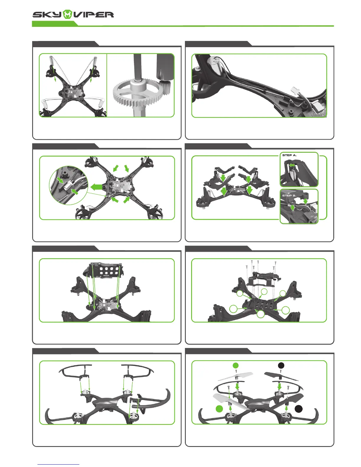
STEP ELEVEN
Press on each propeller and secure each with type B screws. Ensure that the
green propeller blades are attached to the front of the drone and the black
propeller blades at the back. Take note of the order of the propellers (B,A,A,B.)
The drone will not fly if the propellers are in the wrong place.
STEP TEN
Attach the four blade guards by pushing the two locator pins into the two holes
around the gear housing. Make sure the pins are fully in and the guard ridges are
flush with the gear housing.
STEP NINE
Place the battery tray over the flight controller board cover and secure it with 6
type A screws. When tightening the screw, ensure that they are firm but not overly
tight, as over tightened screws will cause the plastic to strip and the screw will
become loose.
STEP EIGHT
Attach the bottom cover to the main body and ensure none of the wires
are protruding.
STEP SEVEN
Attach the four arm covers to the main body ensuring no wires protrude from
the sides. You must connect the hook of the arm covers to the motor housing
before easing into place. The front arm covers are curved and contain the green
LED windows. The red LED covers go in the rear.
STEP SIX
Press the 4 LED’s into the drone arms and ensure that the green LED’s are
attached to the curved front arms and red LED’s are connected to the rear
straight arms. Try not to move the wires connecting the LEDs too much, as the
soldered connections to the flight board are very delicate.
STEP FIVE
Neatly tuck the motor wires into the guides in the center of each arm of the drone.
Then guide the wires around the post and carefully tuck away any remaining wire
without crimping it.
STEP FOUR
Slide each of the motors into the motor casing until the gears mesh properly with
the large gears. Take your time to check each motor before moving onto the next.
FRONT.
4TH
6TH
1ST
3RD
5TH
B
A
A
B
2ND