7
2.1 Control Panel
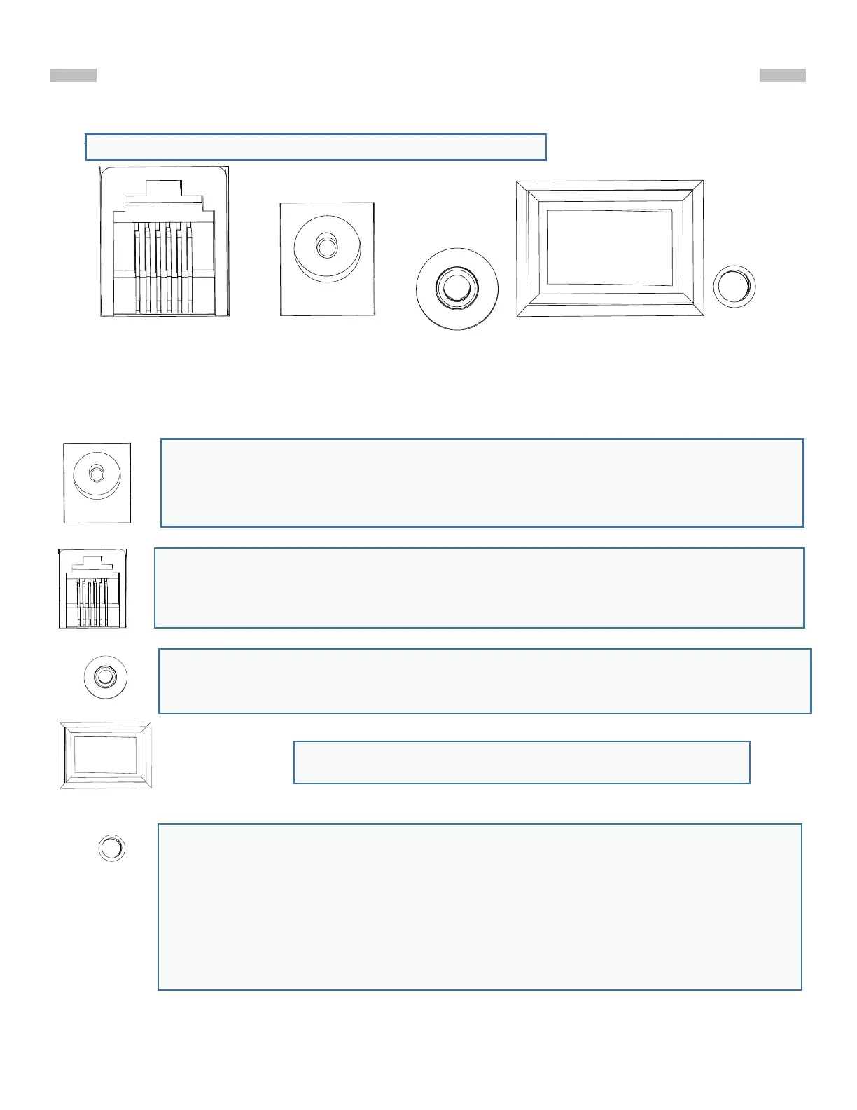
The control panel of the AZGTi mount is shown below:
2.2 Panel Interface Components:
PART II : ELECTRONIC CONTROL INTERFACE
POWER: This is an outlet from which the mount and the hand control get the exter-
nal power supply.
HAND CONTROL: This RJ-12 6-pins outlet is for connecting the SynScan hand
controller.
SNAP:This is a stereo outlets for connecting with a camera’s shutter control ports.
The SynScan hand control can control the cameras to take pictures automatically
via these interfaces.
ON/OFF Switch: Turns the power to the mount and hand controller on and o.
Power LED: The power LED serves as a power-on indicator and provides other
statuses.
1. Steady on: Internal Wi-Fi is o.
2. Intermittent one ash: Internal Wi-Fi is on.
3. Intermittent two ashes: App has connected to internal Wi-Fi.
4. Intermittent three ashes: Internal control board has entered rmware update
mode.
Hand Control
Power
SNAP
ON OFF
LED
Fig. 2.1
Netz-LED:
Die Power-LED dient als Einschaltanzeige und liefert weitere Zustände an.
1. Leuchtet konstant: Das interne Wi-Fi ist ausgeschaltet.
2. Intermittierendes einmaliges Blinken: Internes Wi-Fi ist eingeschaltet.
3. Zweimaliges Blinken mit Unterbrechungen: Die App hat sich mit dem internen Wi-Fi verbunden.
4. Intermittierendes dreimaliges Blinken: Die interne Steuerplatine ist in den Firmware-Update Modus
Schaltet das Gerät AN/Aus
SNAP:
Dies ist ein Stereo-Ausgang zum Anschluss an die Auslösesteuerungsanschlüsse einer Kamera.
Die SynScan Handsteuerung kann die Kameras steuern, um automatisch Bilder aufzunehmen
über diese Schnittstellen
HANDSTEUERUNG:
Dieser 6-polige RJ-12-Ausgang ist für den Anschluss der SynScan-Handsteuerung
Controller.
POWER:
Dies ist eine Steckdose, über die die Montierung und die Handbedienung mit
externer Energie versorgt werden kann.
Siehe angefügte Erklärungen
 Loading...