SKYJACK, Page 16
September 2007
SJ 40T & SJ 45T
Section 2 - Operation Component Identification
2.5 Component Identification
The following descriptions are for identification,
explanation and locating purposes only.
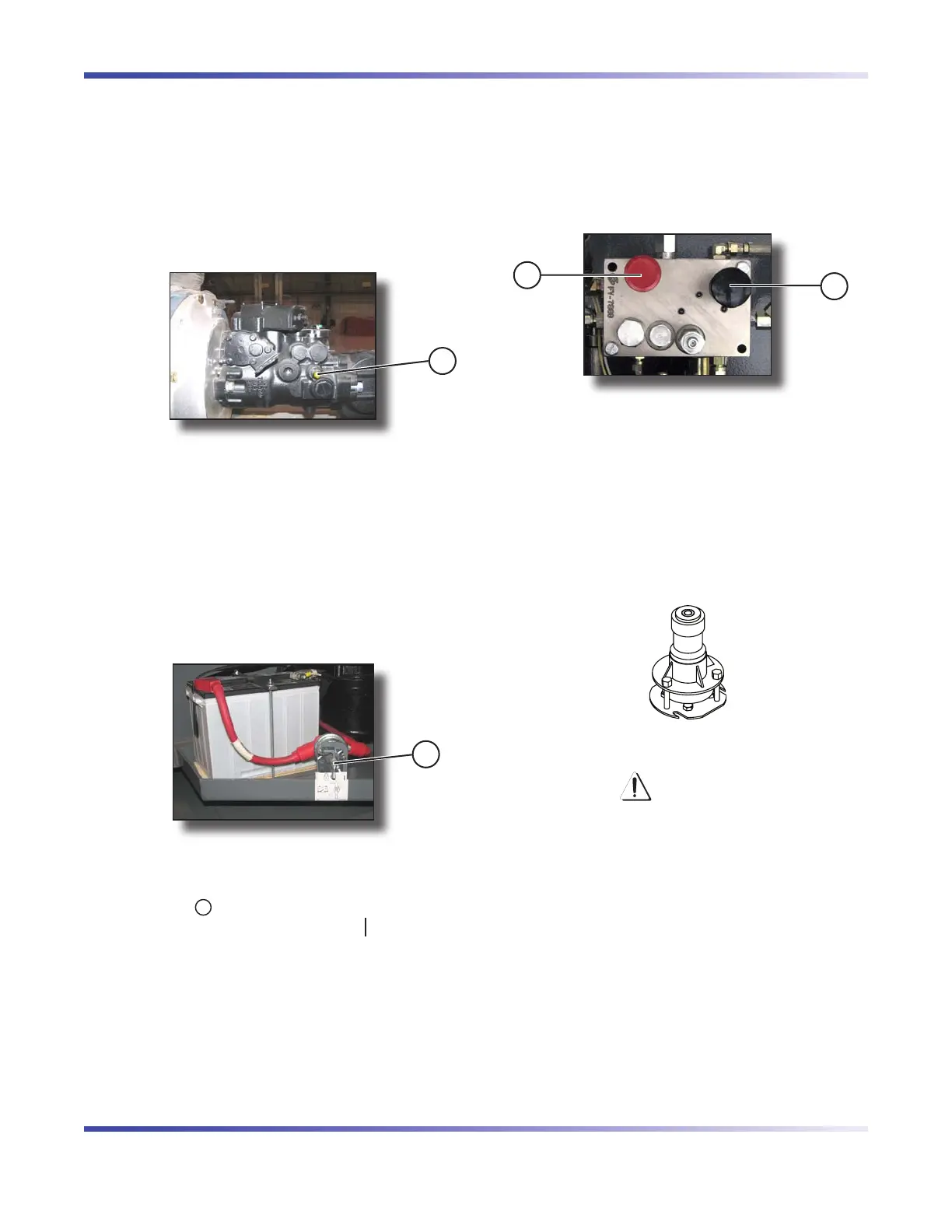
2.5-1 Drive Bypass Valve
This valve is located on the inboard side of the drive
pump and can be identified with a yellow paint mark
on it.
1
Figure 2-1. Drive Bypass Valve
Drive Bypass Valve with Override Stems
- This valve, when loosened two revolutionsThis valve, when loosened two revolutions
counterclockwise, is used to override drive relief
valves so that the aerial platform can be loaded or
unloaded from a trailer using a winch line.
2.5-2 Main Power Disconnect Switch
This switch is located in the engine compartment near
the battery.
1
Figure 2-2. Main Power Disconnect Switch
Main Power Disconnect Switch - This switch,
when in “ ” off position, disconnects power
to all circuits. Switch must be in “ ” on position
to operate any circuit. Turn switch off when
transporting aerial platform.
1.
1.
2.5-3 Brake System
The brake system is located in the control compartment.
The brakes must be manually disengaged before
pushing, winching or towing. Refer to Section 2.13-1
for procedure on how to release brakes manually. The
system contains the following controls:
2
1
Figure 2-3. Brake System
1. Brake Hand Pump
2. Brake Auto Reset Valve Plunger
2.5-4 Tilt Switch
The tilt switch is located on top of the base control
console. It is designed to prevent driving when aerial
platform is on a slope greater than a predetermined
limit.
Figure 2-4. Tilt Switch
WARNING
If aerial platform becomes tilted causing
alarm to sound, the platform must be fully
lowered immediately. Ensure that aerial
platform is on a firm level surface before
operating the aerial platform. Refer to
Section 2.15 for instructions regarding
recovery from an inclined position.

 Loading...