EasyManua.ls Logo

Skytech AFVK-SP Series - User Manual

Skytech AFVK-SP Series
7 pages
Print Icon
To Next Page IconTo Next Page
Loading...
Trouble Shooting Guide
for
AFVK-SP Series Valve Kit
(AF-4000 Series Gas Valves)
AFVK-SP, AFVK-SP-H/L, AFVK-SP-MH/L
f i r e - p a r t s . c o m
Question and Answer IconNeed help?

Do you have a question about the Skytech AFVK-SP Series and is the answer not in the manual?

Summary

General Lighting Information

Lighting Procedure

Procedure for activating the pilot assembly and burner ignition using the ON button and radio frequency signal for gas valve operation.

Control Module Fault Codes

The control module acts as the system's brain, indicating faults via audible beeps.

Fault Codes

Ignition Safety

Indicates a failure in the ignition sequence or burner ignition within 60 seconds, signaled by one beep per second.

Sensor Safety

Signaled by constant beeping, this fault occurs when a flame is detected but not present, or if the sensor wire is shorted.

Thermal Safety

Indicates overheating where internal module temperature exceeds 170 degrees F, signaled by four beeps every two seconds.

Other Symptoms

Burner Flame Modulation Issues

Troubleshooting steps for when the burner flame does not modulate correctly or operates backward.

Flame Height Adjustment

Addresses issues with flame height appearing too high (HI) or too low (LO) and gas type conversion.

No Audible Beep from Module

Troubleshooting steps when the control module does not emit an audible beep when using the transmitter.

Burner Not Lighting (Pilot ON)

Diagnoses why the main burner fails to ignite when the pilot light is already on.

Specifications

Gas Connections

Details the NPT thread sizes for main gas inlet/outlet and optional side inlet/outlet connections.

Pilot Gas Connections and Flow

Specifies the connection size and flow rate for pilot gas.

Ambient Temperature Range

Defines the operational temperature range for the valve kit in Fahrenheit and Celsius.

Voltage and Pressure Ratings

Lists the required DC voltage for operation and the maximum pressure rating.

Approvals and Part Numbers

Provides CSA approval details and specific part numbers for the valve and module.

Procedures For Qualified Technicians

Test Voltage to Gas Valve

Procedure for testing the voltage supply to the gas valve using a multimeter.

Test Burner Coil Resistance

Method for testing the resistance of the burner coil at the gas valve to check its functionality.

Test Static and Operating Line Pressure

Guidance on checking gas line pressure differences between static and operating states.

Overview

This document is a troubleshooting guide for the AFVK-SP Series Valve Kit, specifically designed for AF-4000 Series Gas Valves. It covers various models including AFVK-SP, AFVK-SP-H/L, and AFVK-SP-MH/L.

Function Description:

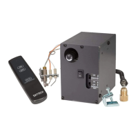
The AFVK-SP Series Valve Kit is a control system for gas fireplaces and other gas appliances, enabling remote and manual operation of the gas valve, pilot light, and flame height. The core of the system is the AF-4000MOD-1 Control Module, often referred to as the "Brain," which manages the valve's operations and incorporates built-in fault codes for diagnostic purposes.

  • AFVK-SP: Features a manual ON/OFF switch, manual HI/LO flame adjustment, and an ON, OFF transmitter for basic control.
  • AFVK-SP-H/L: Includes a manual ON/OFF switch, a solenoid for HI/LO flame adjustment, and an ON, OFF, HI, LO transmitter for more granular control.
  • AFVK-SP-MH/L: Offers a manual ON/OFF switch, a motor drive for variable flame adjustment, and an ON, OFF, HI, LO transmitter, providing the most precise flame control.

The system operates by receiving radio frequency signals from a transmitter. When the ON button is pressed, the module powers the pilot assembly, initiating sparking and opening the gas valve to the pilot. Sparking ceases once the sensor detects a flame, and burner ignition is complete. The "Continuous Pilot" feature allows for the activation of a standing pilot.

Important Technical Specifications:

  • Main Gas Connections: 3/8 inch NPT thread on all Inlet and Outlet connections. An optional 1/2 inch NPT Side Inlet and Outlet is available.
  • Pilot Gas Connections & Flow: Connection Size: 7/16-24 UNS. Flow: Approximately 5,250 Btu/hr at 7.0 inches Water Column (WC) maximum. Connections are located on the side and back of the valve.
  • Ambient Temperature Range: 0°F to 175°F (-18°C to 79°C).
  • Voltage: 6 Volt DC Powered.
  • Maximum Pressure: 1/2 psi.
  • Approvals: CSA International Report Number Valve: 224930-156330, Module: 224930-1998843.
  • Battery Voltage (System): A minimum of 5.3 volts DC in the battery pack is required for proper operation. If using an AF-4000ADP24 DC Adapter, a minimum of 6.75 to maximum of 8.25 volts DC is needed.
  • Battery Voltage (Transmitter): A minimum of 9.0 volts DC is required for the transmitter.
  • Spark Gap at Pilot Assembly: Should be 3mm (1/8 inch) from the hood to the first spark electrode.
  • Burner Coil Resistance: When tested at the gas valve, the coil resistance should read between 990 Ohms and 1230 Ohms.
  • Static Pressure: Natural Gas: 7.0" - 12.0" WC. LP Gas: 11.0" - 14.0" WC.
  • Operating Pressure: Natural Gas: 4.7" WC. LP Gas: 10-14" WC.

Usage Features:

  • Transmitter Control: The system can be operated remotely using a transmitter, with models offering ON/OFF, HI/LO, or variable flame adjustment.
  • Manual Control: A manual ON/OFF switch is present on the valve kit for direct control.
  • Continuous Pilot: Allows for the activation and use of a standing pilot.
  • Gas Type Conversion: Valve kits are shipped for Natural Gas (NG) but can be converted to LP gas by following a specific procedure, including checking the regulator stem and using the correct orifice.
  • Troubleshooting via Fault Codes: The control module emits audible beeps (fault codes) to indicate specific problems, aiding in diagnosis.
    • Ignition Safety (1 beep every 1 second): Indicates the ignitor will not spark or the burner has not ignited within 60 seconds.
    • Sensor Safety (4 beeps every second / constant beeping): Occurs when the sensor detects a flame but none is present, or if the flame (S) sensor wire is shorted to ground.
    • Thermal Safety (4 beeps every 2 seconds): Indicates internal module temperature exceeds 170°F.

Maintenance Features:

  • Pilot Assembly Cleaning: Electrodes should be clean and free of soot build-up. Steel wool can be used for cleaning.
  • Wire Connection Checks: Regular inspection of pilot wires ("I" for Ignitor, "S" for Sensor), 8-Pin connector (orange/white to Pilot, green/white to Main, black for ground), and 4-pin connector from module to battery pack is crucial.
  • Spark Gap Verification: Ensure the spark gap at the pilot assembly is correctly set to 3mm (1/8 inch).
  • Ceramic Insulator Inspection: Check for cracks in the white ceramic insulators at each spark electrode; replace the pilot assembly if cracked.
  • Battery Voltage Monitoring: Regularly check battery voltage in both the battery pack and the transmitter to ensure they meet minimum requirements.
  • Transmitter Learning Procedure: If the module does not respond to the transmitter, the transmitter may need to be re-learned to the module. This involves pressing the "Learn" button on the module and then the "ON" button on the transmitter.
  • Clearing Module Memory: If a transmitter cannot be learned, the module's memory can be cleared by holding the "Learn" button for 10 seconds.
  • Gas Line Pressure Checks: For qualified technicians, procedures are outlined to test static and operating line pressure to ensure proper gas flow.
  • Burner Coil Resistance Test: Qualified technicians can test the resistance of the burner coil at the gas valve to determine if the valve can open or close correctly.
  • Voltage Test to Gas Valve: Qualified technicians can test the voltage to the gas valve (MAIN and PILOT connections) to diagnose module functionality.
  • Module Placement: The control module must remain inside the valve box and in a cool location to prevent overheating. If glass doors are installed, they should be fully opened during operation.

Skytech AFVK-SP Series Specifications

General IconGeneral
BrandSkytech
ModelAFVK-SP Series
CategoryControl Unit
LanguageEnglish