Rev. 10/19/11
3
AFVK-SP Series Valve Kit
Trouble Shooting Guide (AF-4000 Series)
AFVK-SP – Manual ON/OFF switch, manual HI/LO flame adjustment & a ON, OFF transmitter
AFVK-SP-H/L – Manual ON/OFF switch, solenoid for HI/LO & a ON, OFF, HI, LO transmitter
AFVK-SP-MH/L – Manual ON/OFF switch, motor drive for variable flame adjustment & a ON, OFF, HI, LO
transmitter
Components that may be installed with Valve Kit:
Standard: Optional:
SP1001 ON, OFF, ON/OFF/Continuous Pilot AFVK-SP-PILOT/60 60” wire leads and pilot
SP1001 H/L ON, OFF, HI, LOW, ON/OFF/ Continuous Pilot tubing
AF-4000BP Battery Pack AF-4000ADP24 6 Volts DC Adapter
AF-4000MOD-1 Control Module (learns 3 transmitters)
In order to trouble shoot any product it is important to understand the basic operation
and functions of that product. The following information will assist you through this
process.
General Lighting Information
Lighting Procedure:
Pushing the ON button sends a radio frequency signal to the module. This sends power to the pilot assembly and the
sparking begins. The gas valve will open, sending gas to the pilot. Sparking stops after the sensor recognizes the
flame and burner ignition is complete. ON/OFF/Continuous Pilot allows you to activate the continuous pilot feature
and allows the use of a standing pilot.
Control Module (AF-4000MOD-1) “Brain” of the system; has built in fault codes:
The module, inside the valve box, controls the operation of the valve kit. If module detects a problem, it will begin
emitting a series of audible beeps (fault codes). The audible beeps indicate a fault and will assist in locating the
problem.
Fault Codes
Ignition Safety – 1 beep every 1 second
Ignitor will not spark / Burner has not ignited within 60 seconds.
Check
• Gas is ON; line is purged of air and no blockage in the
pilot and main lines.
• Pilot assembly electrodes are clean, no soot build-up (clean
with steel wool if needed).
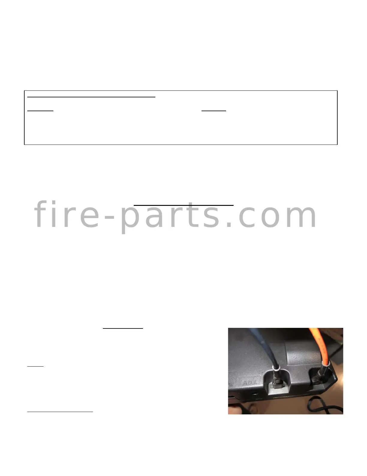
Check Wire Connections
• Pilot wires –“I” (Ignitor) and “S” (Sensor) wires connected