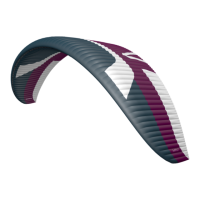
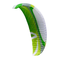
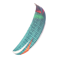
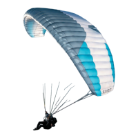
PRO GUIDE // MINT
Technical Data | Line System 5
2 DESCRIPTION
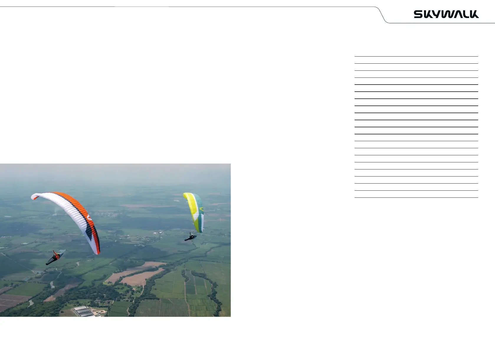
The MINT was designed for experienced XC pilots as well as for competition rookies.
The compact design in combination with the 2-line technology combines the easier
flight characteristics of C-class gliders with the performance of higher-class wings.
Furthermore you have the advantage of being able to control the wing more easily
and fly it more efficiently in accelerated flight.
This makes the MINT suitable for ambitious pilots who want a wing with maximum
performance, but the simpler flight characteristics of a more compact wing.
PILOT REQUIREMENTS
The MINT is for pilots who master the exit of abnormal flight conditions, who fly actively
and regularly, and who understand the implications of flying a paraglider with reduced
passive safety.
SCOPE OF DELIVERY
The MINT comes standard with GUARDBAG, Packing Tube and “BASIC GUIDE”.
3 TECHNICAL DATA
Size
Cell number
Area flat (m²)
Wingspan flat (m)
Aspect ratio flat
Area projected (m²)
Wingspan projected (m)
Aspect ratio projected
min. profile depth (cm)
max. profile depth (cm)
Middle line length without risers (m)
Line consumption (m)
Weight (kg)
Take-off weight, certified from-to (kg)
Winch certified
JET FLAP Technology
Paramotor homologation
Accelerator
Maximum speed bar travel (mm)
Brake line travel max. (cm)
Trimmers
Number of seats
4 LINE SYSTEM
The layout of the suspension points is designed for optimal load distribution and a long
lifespan. With all considerations and calculations however, our focus is always on safety.
The mix of materials used on the lines of the MINT is an ideal combination of durability,
low stretch and low drag.
The skywalk MINT has 3 A-, 3 B- and 1 stabilo line. The main-stabilo is connected with the
A2-riser. The brake lines are not load-bearing and lead from the trailing edge over the main
brake lines through the brake pulleys on the A2-risers to the brake handles.
A marking on the main brake line indicates the position of the handle attachment.
This setting should not be lengthened, for example, to provide more brake travel in extreme
flight situations or during landing, nor shortened such that the glider is flown constantly
with some brake on.
4 Description
75 85 95 105 115 125
68 68 68 68 68 68
20,26 21,38 22,70 24,20 25,67 26,94
11,34 11,65 12,01 12,40 12,77 13,08
6,4 6,4 6,4 6,4 6,4 6,4
17,29 18,24 19,37 20,65 21,90 22,98
9,22 9,48 9,76 10,08 10,38 10,64
4,92 4,92 4,92 4,92 4,92 4,92
54 56 58 59 61 63
220 226 233 240 248 254
7,08 7,28 7,50 7,74 7,97 8,17
202 208 215 222 229 235
4,30 4,45 4,60 4,80 5,10 5,30
55-75 65-85 75-95 85-105 95-115 105-125
yes yes yes yes yes yes
no no no no no no
no no no no no no
yes yes yes yes yes yes
160 160 180 180 180 180
57 59 62 65 68 70
no no no no no no
1 1 1 1 1 1