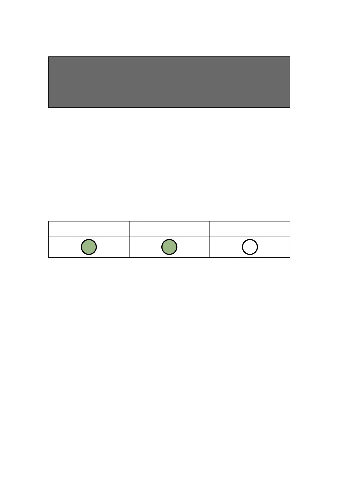
Press button A once in quiescent/normal state to enter this menu. LEDs 1 & 2 will
show the signal/connectivity status of your paths.
LEDS BELOW SHOW FOR RADIO PATHS. ONCE PLUGGED IN, LAN
CONNECTED DEVICES WILL SHOW
GREEN = GOOD CONNECTION / AMBER = POWERED BUT NO DATA
CONNECTION
• Solid green = good signal
• Flashing green = acceptable signal
• Flashing amber = emergency, only/low signal available (move aerial)
• Flashing red = SIM not ready/no signal available (move aerial).
• Red = error
Figure 4 - Connectivity
LED 1 - Primary Path
LED 2 - Secondary Path
(if Applicable)
LED 3 - N/A
PIN TRIGGERING
For this operation the device is triggered by removing or applying zero volts to input
terminals 1-12. No external pull-up resistors will be required. This is generally
achieved via the digital communicator outputs of a control panel. On receiving an
input to the pins terminals the unit will signal alarm conditions and will generate the
relevant messages and forward them via the Gemini Global Platform to the ARC.
Installers are advised that the intended use should avoid situations where the rate of
trigger exceeds the rate at which messages are received at the ARC receiver.
Figure 5 - Example of pin triggering wiring


 To Next Page
 Loading...